background image

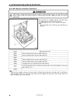
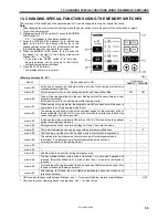
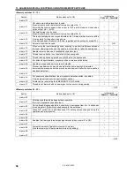
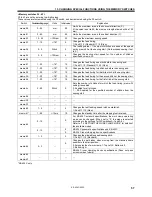
10. STANDARD ADJUSTMENTS

48

KE-434C,435C

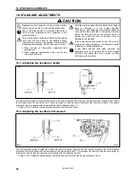
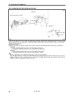
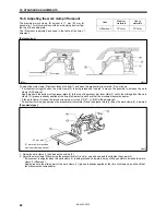
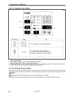
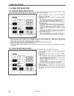
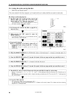
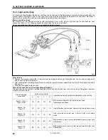
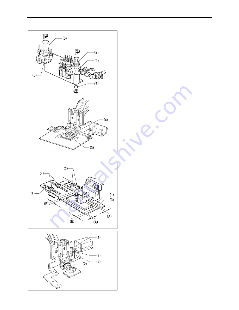
10-16. Adjustment of air pressure (for pneumatic)

1. Air pressure should be 0.5 Mpa.

The air pressure can be adjusted by pulling up and turning the
control knob (2) on the integrator (1).
After adjustment is complete, push the control knob (2)
downward to lock it.

2. Adjust the air pressure for the reversal cylinder to stay within

such a range that the presser crank (4) rotates reversely when
pressing the sewing material with the pressure plate (3).
(Approx. 0.3 Mpa)
For adjustment, pull up and, turn the control knob (6) on the
air regulator (5).
After adjustment is complete, push the control knob (6)
downward to lock it.

3. If water stands in the bottle of the integrator (1), turn the drain

cock (7) in the direction indicated by an arrow to drain the
water.

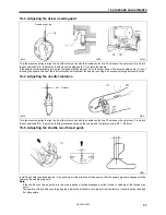
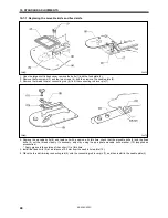
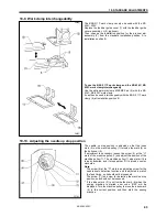
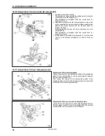
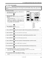
10-17. Adjustment of inner clamping device

Adjustment of the positioning plates

Loosen the screws (2), and adjust the position of the positioning
plate R (3) so that the label (1) can be evenly laid out between
the front and back seams (A).
Next, loosen the screws (4), and adjust the position of the
positioning plate L (5) so that the presser plate can be evenly laid
out between the left and right seams (B).

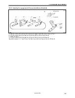
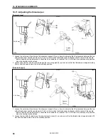
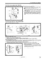
Adjustment of the presser crank horizontal position

Loosen the nut (3) and push in or pull out the adjusting bolt (4) so
that the presser crank (2) can be horizontal when the reversal
cylinder piston rod (1) is moved to the left extreme.

2624Q

2623Q

2621Q

Increase pressure

Increase pressure

2622Q

Summary of Contents for KE-434C

Page 1: ...ease read this manual before using the machine Please keep this manual within easy reach for quick reference ELECTRONIC LOCKSTITCH PATTERN TACKER ELECTRONIC LOCKSTITCH PATTERN TACKER WITH STEPPING FOOT INSTRUCTION MANUAL ...

Page 2: ... safe operation of this machine and to prevent accidents and injury to yourself or other people The meanings of these indications and symbols are given below Indications DANGER The instructions which follow this term indicate situations where failure to follow the instructions will almost certainly result in death or severe injury CAUTION The instructions which follow this term indicate situations...

Page 3: ...ctrical storm turn off the power and disconnect the power cord from the wall outlet Lightning may cause problems with correct operation Installation Machine installation should only be carried out by a qualified technician Contact your Brother dealer or a qualified electrician for any electrical work that may need to be done The sewing machine weighs more than 56 kg The installation should be carr...

Page 4: ...e to wear protective goggles and gloves when handling the lubricating oil and grease so that they do not get into your eyes or onto your skin otherwise inflammation can result Furthermore do not drink the oil or eat the grease un der any circumstances as they can cause vomiting and diarrhoea Keep the oil out of the reach of children Maintenance and inspection Maintenance and inspection of the sewi...

Page 5: ...2 3 High temperature warning display Safety devices Eye guard Finger guard Thread take up cover Thread take up solenoid cover Belt cover Frame side cover etc 4 Be sure to connect the ground If the ground connection is not secure you run a high risk of receiving a serious electric shock and problems with correct operation may also occur 5 Direction of operation 2743Q Finger guard Eye guard Thread t...

Page 6: ...0 STANDARD ADJUSTMENTS 36 10 1 Adjusting the needle bar height 36 10 2 Adjusting the needle bar lift amount 36 10 3 Adjusting the driver needle guard 37 10 4 Adjusting the needle clearance 37 10 5 Adjusting the shuttle race thread guide 37 10 6 Adjusting the thread take up amount 38 10 7 Adjusting the movable knife 39 10 8 Adjusting the work clamp lift amount 42 10 9 Work clamp interchangeability ...

Page 7: ...se lever 7 EMERGENCY STOP switch 8 Pulley 9 Spool stand 10 Thread take up lever 11 Wiper solenoid cover 12 Thread wiper switch Safety devices 13 Finger guard 14 Eye guard 15 Thread take up cover 16 Belt cover 17 Frame side cover 18 Thread take up solenoid cover 2477Q 2594Q KE 435C 2476Q KE 434C Solenoid specifications KE 434C Pneumatic specifications Specifications with inner clamping device ...

Page 8: ...ping foot lift amount 18 mm Stepping foot stroke 0 mm 3 8 mm Safety device built in stopping mechanism Data storage method P ROM Any sewing pattern can be added using PS 3000 Number of user programs 16 Number of cycle programs 4 Number of stored data Up to 100 patterns can be added Total number of stitches of stored data which can be added is within 10 000 Motor Three phase 400W induction motor We...

Page 9: ...of stitches 56 42 56 Sewing patterns Uses Square tacking Bullet nose tacking Round tacking Number of stitches 63 42 63 Sewing patterns Uses Heart shaped tacking Half moon tacking L shaped tacking Number of stitches 70 64 28 Note when creating additional data When sewing data with a small number of stitches 15 stitches or less is sewn repeatedly short cycle operation the upper shaft motor may overh...

Page 10: ...away from any moving parts Furthermore do not excessively bend the cable or secure it too firmly staples otherwise there is the danger that fire or electric shocks could occur Be sure to connect the ground If the ground connection is not secure you run the risk of receiving a serious electric shock and problems with correct operation may also occur Install the belt covers to the machine head and m...

Page 11: ...t it does not fall down 2 Install the control box with the four accessory bolts 4 spacers 5 flat washers 6 and nuts 7 as shown in the illustration above Use two nuts 7 at each installation location and make sure that both nuts are tightened 3 Close the covers panel mounting assembly 2 and main P C board mounting plate 3 and tighten them with the screws 1 The main P C board mounting plate 3 will be...

Page 12: ...abs of the oil pan 2 into the holes for the cushions 1 and then secure it in place with the five nails 3 so that the oil pan 2 is not at an angle 2 While pushing the oil pan 2 down from above screw in the oil container 4 3 5 Installing the cushions Place the two cushions 1 into the holes in the work table so that the notches are aligned with the tabs in the oil pan and secure them in place with th...

Page 13: ...g plate is not installed 3 7 Installing the machine head 1 Insert the head hinges 1 into the machine head so that they are parallel and then secure them with the two set screws 2 2 Place the machine head gently on top of the rubber cushions 3 and cushions 4 Note Pull the cords 5 out as shown in the illustration above in order to prevent them from being clamped by the machine head 3 Install the hin...

Page 14: ...rest Tap the head rest 1 into the table hole Note Tap the head rest securely into the table hole 3 9 Installing the liquid cooling tank optional 1 Remove the rubber plug and then push the liquid cooling tank 1 2 Tighten it with the set screw 2 2497Q 2498Q ...

Page 15: ...op or the bottom of the work table 3 Insert the connector cord 5 into the control box through the hole at the side of the box Refer to 3 12 Connecting the cords for details on connecting the cord 4 Secure the connector cord 5 with the staples in three places 3 11 Connecting the ground wire CAUTION Be sure to connect the ground If the ground connection is not secure you run the risk of receiving a ...

Page 16: ...3 INSTALLATION 10 KE 434C 435C 3 12 Connecting the cords 2744Q 2502Q 2503Q 2504Q ...

Page 17: ... the ground connections are secure in order to ensure safety 8 Securely connect connectors P1 to P8 P11 P14 for pneumatic and P18 as indicated in the table below Note Check that the connector is facing the correct way and then insert it firmly until it locks into place Furthermore lock the cord clamp at the top Machine head connectors Connection location No of pins Cord mark Connection location on...

Page 18: ...socket properly Note If the PROM has been replaced press the RESET switch 17 while turning on the power in order to initialize the memory All of the user programs cycle programs and memory switches which have been recorded will then be cleared The PROM which is installed at the time of shipment from the factory does not include any sewing data If you try to change the program number without replac...

Page 19: ...ht work clamp mode can be used by changing over the air tube connections Refer to 14 Setting the work clamp mode 0746Q KE 434C Pneumatic work clamp Upper knob Lower knob Switch 0319Q Reverse work clamp 0023Q KE 435C 0433Q 0434Q Cylinder L Cylinder R Reversal cylinder Stepping cylinder Upper knob Lower knob Switch Cylinder L Cylinder R ...

Page 20: ...ng the machine The recommended installation position is shown in Figure 1 3 Install the ground cord 5 to the machine head 4 Install the air unit 6 to the valve setting plate 2 with two screws 1 5 Connect the air hose 7 6 Adjust the air pressure Refer to 10 16 Adjusting the air pressure When installing to a beam 1 Make holes in the beam as shown in the illustration above Button hole diameter is 5 4...

Page 21: ...Pneumatic work clamp KE 434C Adjust the control knobs so that the left and right work clamps both operate at the same speed Valve 1 and 2 Reverse work clamp KE 434C First adjust the speed for the reverse work clamp Valve 1 Next turn on the power and then adjust the speed of the left work clamp Valve 2 Adjust the control knobs so that the lowering speed of the left work clamp becomes faster than th...

Page 22: ...foot switch support plate B 13 is used in a back to front position it can be used as shown in Figure B 1 Remove the screw 14 and rubber plug 15 Note that the spring 16 will come out when the screw 14 is removed 2 Turn foot switch support plate B 13 back to front and then install it with the bolt 17 spring washer 18 and flat washer 19 as shown in Figure B Note If using the foot switch without insta...

Page 23: ...ate 3 so that the X feed lever cap 4 sits on top of the needle sub plate 3 3 Install the needle sub plate 3 with the four screws 5 4 Loosen the screws 2 and make fine adjustments to the height of the needle sub plate 3 so that it is at the same height as the needle plate 6 5 Provisionally secure the two auxiliary plate supports 7 with the washers 8 and the screws 9 and 10 and then firmly tighten t...

Page 24: ...tion manual and then install the spool stand 1 at the right side of the work table 3 18 Installing the eye guard CAUTION Attach all safety devices before using the sewing machine If the machine is used without these devices attached injury may result Install the eye guard assy 2 to the face plate 1 with the two screws 3 2509Q 2510Q ...

Page 25: ...he oil sight glass If oil is not added and the oil drops below this level there is the danger that the machine may seize during operation Note 2 Be sure to let the machine operate for a while after adding the oil Note 3 If there is no more oil on the felt of the shuttle race base problems with sewing may result so add oil to the felt until it is slightly soaked Note 4 Use only specified Brother oi...

Page 26: ...en pressed 5 BOBBIN WIND switch Press this switch to wind the lower thread 6 SELECT switch Use this switch to select a menu program number X and Y feed speed and counter Each time the switch is pressed one of the menu indicators 7 to 11 illuminates and the setting for that menu item appears in the display 14 The illuminated indicator changes as follows each time the switch is pressed PROGRAM NO in...

Page 27: ... the SELECT switch 6 is pressed to shown the speed setting 11 COUNTER indicator Illuminates when the SELECT switch 6 is pressed to show the bobbin thread or production counter setting 12 DISPLAY SET switches Used to change the menu details which are displayed in the window 14 13 User program switches Used to set and select user programs 14 Display window This display window will indicate the curre...

Page 28: ...is completes the setting of the program number 5 2 2 Setting the X scale and Y scale 3 Depress the foot switch to the second step Note For two pedal foot switch depress the work clamp switch to lower the work clamp before depressing the start switch 1 Press the SELECT switch 6 until the X scale or Y scale indicator illuminates 2 Press the DISPLAY SET switches 12 until the desired scale setting is ...

Page 29: ...r il luminates 2 Press the DISPLAY SET switches 12 until the desired speed setting is flashing in the display window Note Be sure to check the sewing pattern refer to page 26 after setting has been completed to make sure that the needle hole does not go out of the area circumscribed by the work clamp 2520Q 2603Q ...

Page 30: ...ght side is depressed sewing starts Two pedal foot switch two steps one step For pneumatic When the work clamp switch left side is depressed to step 1 the work clamp on one side is lowered and when it is pressed to step 2 the work clamps on both sides are lowered The work clamp lowering pattern can be set to a variety of different patterns Refer to 14 SETTING THE WORK CLAMP MODE When the start swi...

Page 31: ...d breakage occurred or the lower thread ran out sewing can be resumed from the point where the thread ended 1 Turn the emergency stop switch 1 clockwise and then pull it out to release the lock 2 Press the RESET switch 2 on the control panel The electronic alarm will stop sounding 3 Press the BOBBIN WIND switch 3 to trim the thread 4 Press the BOBBIN WIND switch 3 once more The work clamp will mov...

Page 32: ...foot switch to the second step Only the feed mechanism will move Check that the needle hole 1 does not protrude past the frame of the work clamp 2 If you depress the foot switch again and keep it depresses after the feed mechanism has started to move the feeding speed will increase If you would like to stop the feed while it is moving press the TEST switch 5 Press the TEST switch The TEST indicato...

Page 33: ...ar as it will go so that the groove is facing toward you and then tighten the set screw 1 7 3 Threading the upper thread CAUTION Turn off the power switch before threading the thread otherwise the machine may operate if the foot switch is depressed by mistake which could result in injury Thread the upper thread correctly as shown in the illustration below If the tension release lever 1 is raised i...

Page 34: ...ps being wound onto the bobbin Release the BOBBIN WIND switch 3 after the machine starts operating If you release the foot switch before winding is completed depress it once more while pressing and holding the BOBBIN WIND switch 3 6 The bobbin presser 1 will automatically return to its original position after a set amount of thread 80 90 of the bobbin capacity has been wound on 7 Release the foot ...

Page 35: ...lled at this time 3 Pass the thread through the lever thread hole 4 and then pull out approximately 30 mm of thread 7 6 Thread tension 7 6 1 Sewing conditions and thread tension Medium materials Heavy materials Use Standard hook Large hook Standard hook Large hook Upper thread 50 or equivalent 30 or equivalent Lower thread 60 or equivalent 50 or equivalent Upper thread tension N 0 6 0 9 1 0 1 3 1 ...

Page 36: ...r thread tension Adjust the thread tension to the weakest possible tension by turning the thread tension nut 1 until the bobbin case will not drop by its own weight while the thread end coming out of the bobbin case is held 7 6 4 Upper thread tension Turn the tension nut 1 main tension to adjust the tension as appropriate for the material being sewn Furthermore turn the thread nut 2 sub tension to...

Page 37: ...ide R 1 to the left The thread take up amount will become greater When sewing thin material move arm thread guide R 1 to the right The thread take up amount will become less 7 6 8 Thread take up amount Loosen the screw 1 and move the stopper 3 57 nut 2 to adjust the operating angle of the thread take up solenoid 3 KE 434C To reduce the thread take up amount move the stopper 2 upward To increase th...

Page 38: ...nate and the program number will flash in the display 2 Depress the foot switch to the 2nd step For two pedal foot switch depress the start switch right side The feed mechanism will move to the starting position and the work clamp will rise Note that if the foot switch is pressed to the 2nd step while the program number is illuminated the machine will start operating 3 Place the material to be sew...

Page 39: ...diarrhoea Keep the oil out of the reach of children Wait until the motor has cooled down before cleaning the air holes The motor may be hot immediately after it has been used and it may cause burns if touched 9 1 Checking the needle Always check that the tip of the needle is not broken and also the needle is not bent before starting sewing 9 2 Cleaning the rotary hook 1 Pull the shuttle race cover...

Page 40: ...more oil on the felt of the shuttle race base problems with sewing may result so add oil to the felt until it is slightly soaked Note4 Use only specified Brother oil Nisseki Mitsubishi Sewing Lube 10N VG10 for the machine oil 1 Fill the arm side oil tank with oil 2 Fill the bed side oil tank with oil 3 Add oil to the felt 1 of the shuttle race base When setting up the sewing machine and when it ha...

Page 41: ...ns the overheating error code E d0 will be displayed and you will not be able to operate the sewing machine 9 6 Cleaning the air holes of belt cover and frame side cover Remove the belt cover 1 and the frame side cover 2 and then clean the air holes 3 After cleaning install the belt cover 1 and the frame side cover 2 If dust collects in the air holes it may cause the motor to overheat The air hole...

Page 42: ...ed to be left on when carrying out some adjustment be extremely careful to observe all safety precautions If any safety devices have been removed be absolutely sure to re install them to their original positions and check that they operate correctly before using the machine 10 1 Adjusting the needle bar height Turn the machine pulley to move the needle bar to the lowest position Then remove the ru...

Page 43: ...urn the machine pulley to align the tip of the rotary hook with the needle center line Then loosen the set screw 1 and turn the eccentric shaft 2 to adjust so that the clearance between the needle and the rotary hook is 0 01 0 08 mm 10 5 Adjusting the shuttle race thread guide Install the shuttle race thread guide 1 by pushing it in the direction of the arrow so that the needle groove is aligned w...

Page 44: ...amount move the stopper 3 upward To increase the thread take up amount move the stopper 3 downward KE 435C To reduce the thread take up amount move the stopper 3 downward To increase the thread take up amount move the stopper 3 upward Note Do not increase the stroke of the thread take up lever any more than is necessary If the sub thread tension is too high the needle thread length may become too ...

Page 45: ... thread trimmer cam 4 3 In this condition turn the machine pulley to align the position of the roller 3 with the mark on the thread trimmer cam 4 4 Loosen the nut 6 and move the connecting rod lever 7 to the left or right to adjust so that the V section A is aligned with the index mark B on the needle plate when in this condition the procedure 3 and the movable knife 5 is pushed to the machine pul...

Page 46: ...n 7 4 Remove the movable knife 8 and replace it with a new one At this time check that the movable knife 8 and the fixed knife 9 cut the thread cleanly If necessary adjust by using the apropriate movable knife washer 10 supplied as accessories Apply grease to the outside of the collar 11 at this time 5 Install the fixed knife 9 at a distance of 0 5 mm from the needle hole plate 12 6 Place the thre...

Page 47: ...Fig 1 B Turn the movable knife in the direction of the arrow while the screw is still tightened C Loosen the screw D Turn the movable knife in the direction of the arrow while the screw is still loosened Repeat above steps A B C and D four or five times to maintain the cutting performance of the knife 0149Q Fig 1 Movable knife Fixed knife 0150Q Cutting edge Cutting edge 2949Q Cutting edge Cutting ...

Page 48: ...already applied at the time of shipment and check that the movement becomes easier If the work clamp 3 cannot be raised or lowered error code E 61 or E 63 will be displayed Check that there is a gap between the presser arm lever plate 2 and the presser plate 4 when the work clamp 3 is lowered Pneumatic type 1 Raise the work clamp 1 and loosen the screws 2 2 Adjust the work clamp lift by moving the...

Page 49: ...he needle up stop position is adjusted so that the index mark 2 on the machine pulley 1 is inside the mark 4 on the belt cover 3 If adjustment is necessary loosen the screw 5 at the U mark of the machine pulley 1 and adjust the position of the machine pulley 1 The machine pulley 1 stops later if it is turned clockwise and it stops earlier if it is turned counter clockwise Note The screw 6 at the D...

Page 50: ...hat the thread wiper is approximately 20 mm from the needle when it is at the standby position Pneumatic type 1 Loosen the set screw 2 and move the wiper arm support 3 up or down to adjust so that the clearance between the top of the thread wiper and the needle point 1 is 2 0 5 mm when the thread wiper is aligned with the center of the needle Before carrying out this adjustment check that the need...

Page 51: ...s illuminated Synchronizer 1 When COUNTER indicator is illuminated Presser sensor ON when presser is lowered For solenoid specification 1The synchronizer display simultaneously displays the needle up signal 3rd digit the 24 section signal 2nd digit and the needle down signal 1st digit H L L H when the sensor is on and L when the sensor is off Needle down signal 24 section signal Needle up signal I...

Page 52: ... the cause may be that an incorrect memory setting may have been made by means of the memory switch for instance In such cases carry out the following procedure to clear the memory and also check the DIP switch settings Method While pressing the RESET switch turn on the power This will clear all of the memory setting Note This operation causes memory switches to be returned to their initial settin...

Page 53: ... SCALE indicator 7 or Y SCALE indicator 8 illuminates 5 Press the DISPLAY SET switches 9 to move the feed mechanism one pulse at a time If the DISPLAY SET switch is pressed while the X SCALE indicator is illuminated the feed mechanism will move to the left If the DISPLAY SET switch is pressed while the X SCALE indicator is illuminated the feed mechanism will move to the right If the DISPLAY SET sw...

Page 54: ...d to lock it 3 If water stands in the bottle of the integrator 1 turn the drain cock 7 in the direction indicated by an arrow to drain the water 10 17 Adjustment of inner clamping device Adjustment of the positioning plates Loosen the screws 2 and adjust the position of the positioning plate R 3 so that the label 1 can be evenly laid out between the front and back seams A Next loosen the screws 4 ...

Page 55: ...amp lift to 3 5 mm 1 Loosen the screw 2 and open the stepping cover 3 2 Loosen the nut 4 and adjust the stepping work clamp connecting rod 5 position When the stepping work clamp connecting rod is raised the lift will increase When lowered the lift will decrease Adjusting work clamp lift to 5 8 mm 1 Turn the upper shaft to set the work clamp to its lowest point Loosen the screw 9 of stepping work ...

Page 56: ...pleted the number being displayed in the display window 6 will become smaller When the number of articles set by the bobbin thread counter have all been sewn 0000 will be displayed in the display window 6 and an alarm will start sounding continuously The sewing machine will not operate during this time even if the foot switch is depressed 6 Replace the bobbin and then press the RESET switch 4 The ...

Page 57: ...Motion when set to ON DIPA 1 Presser does not automatically lift after sewing is completed DIPA 2 Pedal mode is switched See 14 Setting the presser mode DIPA 3 User program mode is available DIPA 4 DIPA 5 The presser does not rise automatically when a split is found DIPA 6 Displays the enlargement reduction ratio in millimeter units instead of as a percentage After changing this setting be sure to...

Page 58: ...down Switch Motion when set to ON DIPB 1 First two stitches are sewn at a low speed of 260 rpm DIPB 2 Last two stitches are sewn at a low speed of 260 rpm DIPB 3 DIPB 4 Last two stitches are sewn at a low speed of 700 rpm DIPB 5 First two stitches are sewn at a low speed of 400 rpm DIPB 6 Low speed sewing is not performed at the start of sewing DIPB 7 The motor operates in reverse when the upper s...

Page 59: ...thes 10 to select the X scale setting that you would like to record 7 Press the SELECT switch 3 The Y SCALE indicator 6 will illuminate 8 Press the DISPLAY SET switches 10 to select the Y scale setting that you would like to record 9 Press the SELECT switch 3 The SPEED indicator 7 will illuminate 10 Press the DISPLAY SET switches 10 to select the speed setting that you would like to record 11 Pres...

Page 60: ...itches for selection Clearing the user programs 1 Switch the machine to recording mode by the procedure in steps 2 of recording a user program 2 Use the DISPLAY SET switches 10 to specify the user program number which is to be cleared of data 3 Press the RESET switch 12 The buzzer will sound and the user program with the number selected will be cleared If you press and hold the RESET switch 12 unt...

Page 61: ...rmally it moves to the starting point after sewing starts memo 03 When sewing using programs the programs which have been set will be sewn in numerical order Cycle sewing mode is set memo 04 The sewing speed will be fixed at the minimum speed for the maximum pitch of the sewing data Set this to ON if you are concerned that variations in pitch may cause changes in the sewing speed memo 05 Increases...

Page 62: ...nd memo 19 For solenoid specifications presser position errors are not detected memo 1A Needle up stop position errors are not detected memo 1b Presser can be moved up and down before the home position is detected Normally the presser cannot be moved up and down until after the home position has been detected memo 1c memo 1d For pneumatic specifications the air pressure detection switch is enabled...

Page 63: ...or the third stitch at the sewing start memo 3A 1 20 7 5 10 Changes the feed timing for the second stitch at the sewing start memo 3b 1 20 7 5 10 Changes the feed timing for the first stitch at the sewing start memo 3c 0 99 Stitch 0 Sets the number of stitches for which the feed timing memo 33 setting is enabled 0 Enabled for all stitches 1 99 Enabled for the specified number of stitches from the ...

Page 64: ...Programs P2 P3 and P4 switches can also be used for programming 5 Press the SELECT switch 3 The PROGRAM No indicator 4 will illuminate and 1 will appear in the display window 10 6 Press the DISPLAY SET switches 11 to select the number for the user program that you would like to record 7 Press the SELECT switch 3 2 will appear in the display window 10 8 Press the DISPLAY SET switches 11 to select t...

Page 65: ...eck the contents of the recorded user program Clearing a cycle sewing program 1 Switch the machine to recording mode by the procedure in step 3 of recording a user program 2 Use one of the P switches user program switches to specify which cycle sewing program to clear Press the P1 switch 9 if you would like to clear cycle sewing program No 1 Pc 1 will be displayed 3 Press the RESET switch 12 The r...

Page 66: ...tings for pneumatic specifications memo 42 Pedal specifications Raising the presser at the sewing end 5 Two pedals Left presser drops when presser pedal is at the 1st step and right presser drops when presser pedal is at the 2nd step Raising is carried out in the reverse order Initial value for inner clamping specifications only Setting used when using the light work clamp function Refer to 14 3 L...

Page 67: ... the home position When the start pedal right side is depressed for a short time 200 ms the right work clamp is lowered and when it is depressed for a longer time the right work clamp is lowered and then sewing starts For the KE 435C the right work clamp is lowered when DIP switch A 2 is ON and the stepping foot is also lowered at the same time 13 Two pedals Two pedal operation raises and lowers t...

Page 68: ...bels at this time 2 After checking that everything is positioned correctly depress the presser pedal to the 2nd step to firmly clamp the article being sewn 3 Press the start pedal to start sewing Other hose connections and corresponding operations The hoses can be connected in combinations other than the one shown above so that only one side of the presser operates in light work clamp mode Cylinde...

Page 69: ...in 4 5 mm left and right from the reference point However note that if a non standard work clamp is being used the reverse stitching area will become smaller 2 When the work clamp 1 reverses after sewing is completed the work clamps are retracted so that they do not touch the needle However sometimes it is not necessary to retract the work clamps if the material is thin In such cases if memory swi...

Page 70: ... motor has operated Turn off the power and then turn the machine pulley to check if the machine has locked up Check the synchronizer connection Check if connectors P11 P12 and P13 are disconnected Check that the correct combination of motor and PROM has been installed E 21 Machine motor operation error Turn off the power and check the ground wire connection E 30 Data is outside possible sewing are...

Page 71: ...n If the error continually occurs contact a qualified service technician E E1 Corrupted EEPROM data or main PROM version has been upgraded Press the RESET switch to reset the error However the data memory switches display and user programs will be reset to the backup data or initialized E E2 Corrupted EEPROM control information data Press the RESET switch to reset the error However the data memory...

Page 72: ...y materials Extra heavy materials Needle hole plate φ2 2 S49980 001 FM φ2 6 S10212 101 E 159610 301 A 152690 401 B Bobbin case assy S59221 001 LC 154339 101 A 154340 101 B Tension spring S48664 001 AN 154341 001 Screw S16492 101 LA 159612 001 A 154342 001 B Spring anti spin S15667 001 LA 159613 051 154663 001 B Bobbin S44633 001 LAN 152685 903 A 152687 902 B Shuttle hook W BOX S59161 991 LF S59162...

Page 73: ...inner clamping device Stepping foot KE 435C 434 1R S42030 001 434 2R S42032 001 434ESF 2R S46544 001 434 1L S42031 001 434 2L S42033 001 154256 101 A 434ESF 2L S46545 001 434 1 S42034 001 434 2 S42035 001 434 R1 S43459 001 434ESF 2 S44942 001 Gauge parts The following are provided as optional gauge parts Each work clamp pair is used in combination with the feed plate directly below them Work clamp...

Page 74: ...6089 001 S Work clamp 156084 001 L 156090 001 S Feed plate Gauge assy 434E MK2 S54984 001 Needle hole plate A S10211 001 AF S51449 001 BZ S41013 001 D S29997 001 E S10212 101 ED S30925 001 F S10213 001 FD S30926 001 FM S49980 001 H S30450 001 L S25127 001 M S34348 001 3 S40217 001 Home position standard plate ...

Page 75: ...me of Parts Code Name of Parts Code Name of Parts Code Work clamp crank LA Accessory Work clamp crank S 154297 001 Work clamp crank SS S04516 001 Work clamp plate holder L Accessory Workclampplateholder S 154291 001 Workclampplateholder S 154291 001 17 2 How to make a sewing pattern Condition 1 and Condition 2 Align the center point for the top edge of the sewing pattern with the center point A at...

Page 76: ...eed plate 1 2 Make the dimensions 6 mm larger than the size of the stitch 3 Measure the size of positioning plate L 2 and positioning plate R 3 shaded section 4 Make the feed plate 1 so that the size overlaps the sizes in 2 and 3 above If the size in step 2 is larger than the size in 3 then use the size in step 2 for processing Condition 1 2 a 77 Condition 3 a 74 2632Q 2633Q Label Stitch Stitch 26...

Page 77: ... of the screw hole in the work clamp plate 2 Make the work clamp plate so that it is 1 5 mm smaller than the size of the seam 3 Make a 1 mm bevel all along the side of the work clamp plate that does not have a ridge line 4 Then make a step of 0 5 mm as shown in the illustration Condition 3 1 Align the stitch with reference point F which is 6 mm above the center of the screw hole in the work clamp ...

Page 78: ...emove the work clamp crank 3 from the work clamp crank holder 2 2 Remove the screw 4 to replace the work clamp plate holder 5 with the optional one and install it with the screw 4 3 Insert the work clamp crank 6 into the work clamp crank holder 2 Then while pulling out the reversal cylinder piston rod 7 Fig 1 set the work clamp crank 6 so that it faces as shown in the illustration align its groove...

Page 79: ...Hook the link return spring properly Work clamp lift amount is incorrect Incorrect position of presser arm lever plate Distance between work clamp and top of needle plate Adjust the work clamp lift amount 42 Clearance between thread wiper and needle tip Adjust the height of the thread wiper 44 The thread wiper is ob structing the needle Thread wiper position Adjust the operating distance of the th...

Page 80: ...s of needle hole plate or bobbin care are damaged Damage File smooth or replace the affected part Clearance between nee dle and rotary hook tip is too great Needle clearance Adjust the needle clear ance 37 Incorrect needle and rotary hook timing Needle bar lift amount Adjust the needle bar lift amount 36 Driver is contacting nee dle more than is nec essary Clearance between driver and needle Adjus...

Page 81: ... guide is not separating the threads Shuttle race thread guide position Adjust the position of the shuttle race thread guide 37 Shuttle race thread guide is separating the threads insufficiently Shuttle race thread guide position Adjust the position of the shuttle race thread guide 37 Upper thread is not prop erly tight Upper thread tension Adjust the upper thread tension 30 Uneven upper thread le...

Page 82: ...read breakage caused by friction when using synthetic threads Fill the tank with silicone oil 100mm2 s This wipes the thread independently of the work clamp operation Three pedal foot switch for pneumatic Work clamp plate OT for KE 435C only Use according to particular sewing needs in order to provide an even clamping force Refer to the separate parts book for further details The switch has an ind...

Page 83: ...INSTRUCTION MANUAL 15 1 Naeshiro cho Mizuho ku Nagoya 467 8561 Japan Phone 81 52 824 2177 Printed in Japan 118 V34 S91V34 202 2002 10 B 1 ...

Reviews: