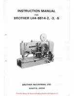
background image

From the library of: Superior Sewing Machine & Supply LLC

Summary of Contents for LH4-B814-2

Page 1: ...INST RUCTION MANUAL FOR BROTHER LH4 B814 2 3 5 BROTHER INDUSTRIES LTD NAGOYA JAPAN From the library of Superior Sewing Machine Supply LLC ...

Page 2: ...g and slowdown A tension pulley allows easy belt adjustment e The machine operates quietly with a minimum of vi bration and has great durability e Longitudial and crosswise rulers are provided as accessories Winding Lower Thread 8 Fitting Bobbin Case into Place 8 Sewing 9 21 Thread Tensions 9 rll Thread Take up Spring Adjustment I0 Cleaning I0 D STANDARD ADJUSTMENTS II 1 eedle and Hook Timing Adju...

Page 3: ...he upper thread runs on the top of the work and only the lower thread on the other side in zigzag form as zigzag stitches formed by a lock stitch zigzag machine A SETTING UP Installation of the Motor Pulley 0 Cutter f Needle bar 8 Face plate Purl stitch 0 Thread retainer 8 Ca m cover 0 Top cover 0 Belt cover 0 Handle f Emergency stop lever Front side Back side The upper thread runs straight under ...

Page 4: ...speed pulley 0 are in line Motor pulleys and V belts for 50Hz and 60Hz areas are different Select the right ones by referring to the table below Sub class Machine Speed Frequency Motor Pulley V belt 8 V belt 0 3200 rpm 50Hz Motor Pulley 50 43 42 60Hz Motor Pulley 60 41 41 2 3 50Hz Motor Pulley 60 41 41 2800 rpm 60Hz Motor Pulley 60 2800 40 41 5 2800 rpm 50Hz Motor Pulley 60 41 41 60Hz Motor Pulley...

Page 5: ...lever and insert the clutch stopper into the stop cam Move flat belt 0 to the inner side ofthe low speed pulley and idle pulley 8 151 Installation of the Pedals and Chains Loosen he_xagonal bolt 0 and fit two pedals 8 and four pedal stops 8 onto support shaft 8 Fasten pedal stops 8 with screws 8 at positions where the pedals will move lightly Connect hook 8 to lower thread cutter lever 0 run chain...

Page 6: ...is the same as the machine center line 2 Installation of the handle Slide handle 8 onto handle shaft 8 and fasten handle 8 to handle lever 8 with nut 8 4 Installation of the sub tension Install the bobbin winder on the bed with screw0 Bobbin winder pulley 0 must be in line with the flat belt Loosen screw 0 and adjust bobbin winder link shaft 0 by turning it so that when bobbin winder link A 0 is p...

Page 7: ... is used a strong buttonhole can be made with a tape at the backside of the material to be sewn altogether I Install tape winder fl on top cam cover I with screws 2 Fasten tape guide rear fa and tape guide front fD to length feed plate 41 by screws e 4 Pass a tape through as per the picture at the above 3 Fasten tape guard front 8 in case of sub class 2 and fasten tape guard front fJ in case of su...

Page 8: ...ove the face plate side cover and belt cover and oil all working parts Pour a drop or two of oil to the arrow indicated points daily Note Use white spindle oil Oiling System Adjustment 8 _ Moreoil Base Less oil A few minutes after the power is switched on adjust oil flow regulator 8 on the right of the base by turning it until oil level can be seen in gauge pipe 0 Oil level falls during sewing 6 H...

Page 9: ...top 5 After a fixed number of stitches are made the machine stops 6 When the left pedal is stepped on the work clamp rises Repeat above steps 3 4 and 5 a few times Use a DP X 5 needle 0 Loosen set screw f hold the need le with its grooved side facing in your direction a nd insert the needle all the way into the needle hole Cotton thread Spring Thread hanger Pass a thread only th roug thread hanger...

Page 10: ...e the bobbin 0 and cut the thread with the thread cutter 8 Turn screw 0 to adjust the bobbin to the correct thread winding volume If the thread winds unevenly on the bobbin 0 loosen screw G and move bobbin winder tension guide f to the left or right as necessary After winding the thread on the bobbin pass the thread in the order shown below Insert the bobbin into the bobbin case Pass the thread th...

Page 11: ...e left pedal and take out the work How to use the cutter locking device Keep cutter lock lever 8 lightly depressed with your finger until the machine stops The cutter will not drop Turn handle 8 after confirming that the needle is not in the work Thread tensions vary with sewing conditions Refer to the following when selecting suitable tensions 1 Lower thread tension ttfoake Spring 0 Turn adjustin...

Page 12: ...justment 1 Thread take up spring height 2 Thread take up spring tension Less tension About 20 30g Adjust the working scope of thread take up spring 0 by loosening set screw 0 and turning the upper thread tension regulator itself Standard range is about 8 mm Adjust the thread take up spring tension by turning tension stud 0 Standar ten ion is about 20 to 30g IBI Cleaning Remove lint and dust from t...

Page 13: ...from the lowest position Never loosen screws 0 in any case 2 Needle bar height 0 Loosen screw 0 and ra ise or lower needle bar f until there is a clearance of about 1 5 to 2 mm between the hook point a nd the top end of the needle eye when hook point f meet the center line of needle 0 3 Clearance between needle and hook point Loosen screws 0 and move hook 0 forward or back until there is a clearan...

Page 14: ...ly 0 2 mm 6 Keep cutter lock arm 8 pulled with one hand and turn the machine pulley with the other hand until cutter 0 falls to the lowest position 2 Work clamp tilt adjustment ___ cl Fabric f Parallel Top of needle plate Loosen screw 8 and turn work clamp support spring shaft 8 until the bottom of work clamp 8 is parallel to the top of the work 4 Turn the machine pulley by hand until the needle b...

Page 15: ...7 44 48 252 28 30 96 46 46 226 30 28 86 48 44 203 32 26 77 50 42 182 34 24 68 52 40 164 36 22 60 54 I See the above table for 119 stitches and look at the Land R columns 2 Loosen thumb screw 0 and raise gear case cover 8 3 Fit change gear 34 onto shaft L 4 Fit change gear 42 onto shaft R in such away that it will engage the other gear 5 After replacing the gears be sure to close gear case cover 8 ...

Page 16: ...titches t Forward Backward Wl Wl Reference line A 1 Adjust reference line A so that the stitches will not be cut by a falling cutter 2 Adjust zigzag stitch width WI with adjusting screw f Right zigzag stitches Reference line B 3 Adjust reference line B so that the right zigzag stitches will not be cut by a falling cutter Bar tacking W2 4 Adjust bar tacking width W2 with adjusting screw 8 Bar tacki...

Page 17: ...ne 3 mm to 3 5 mm Thick reference line 5 Less than 3 mm Thin reference line 3 mm to 5 mm Thick reference line Loosen screw 8 and install scissors D 8 as close to the work clamp as possible If the scissors are positioned too high the thread end remains on the work after the thread is cut If the thread end is not sewn into stitches it is because the scissors open either too soon or too late Loosen s...

Page 18: ...utch stopper positively 4 Clutch pawl A and B adjustments Clutch pawl A adjustment 2 Clutch start lever clearance Loosen nut 0 and turn bolt 8 to adjust the clearance between clutch lever pin 8 and bolt 0 to about 0 5 to 1 0 mm at the machine stop position 3 Stop spring A tension f3 Turn nuts f and 8 until the lowerend of stop spring shaft 0 is about 4 5 to 5 mm out of the bottom of nut 0 Loosen b...

Page 19: ...ad end remains Upper thread scissors Refer to instructions I r Height of scissors D t fo_r upper hread 15 at start of sewing too high S CISSOrS adjUStment r Needle bent or blunt r Needle Replace needle 7 Needle installed Needle direction Put needle in the Stitches skip r improperly r height correct direction and 7 height Wrong upper threading 1 Upper threading r Pass upper thread 7 correctly Lower...

Page 20: ...__ 118 814 2 3 5 192814 3 02 Printed in Japan From the library of Superior Sewing Machine Supply LLC ...

Reviews: