


4-28
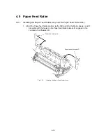
4.15 PCBs
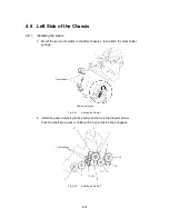
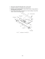
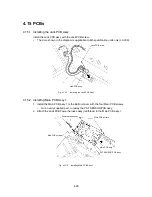
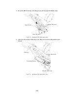
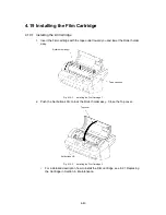
4.15.1 Installing the Jack PCB Assy
Install the Jack PCB assy with the Jack PCB screw.
∗
The Core shown in the diagram is applicable to EU-specification units only (LX-300).
Jack PCB assy
Jack PCB screw
Fig. 4.15-1
Installing the Jack PCB Assy
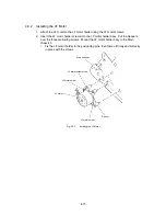
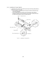
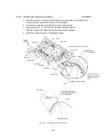
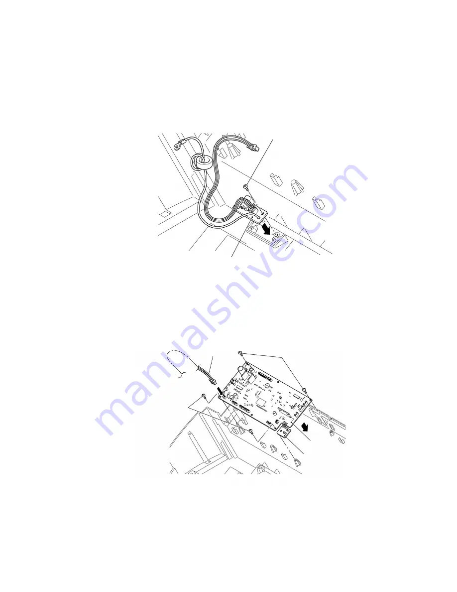
4.15.2 Installing Main PCB Assy 1
1. Install the Main PCB assy 1 to the Bottom cover with the four Main PCB screws.
∗
On a newly supplied part, cut away the PST SENSOR PCB assy.
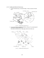
2. Attach the Jack PCB Power harness assy (red/black) to the Main PCB assy 1.
Power harness assy
Main PCB screws
Main PCB screws
PST SENSOR PCB assy
Main PCB assy
Fig. 4.15-2
Installing Main PCB Assy 1
Summary of Contents for LX-1200
Page 1: ...SERVICE MANUAL MODEL LX 1200 LX 300 ...
Page 2: ...COOL LAMINATOR SERVICE MANUAL MODEL LX 1200 LX 300 ...
Page 5: ...Chapter 1 SPECIFICATIONS ...
Page 9: ...Chapter 2 MECHANISMS ...
Page 20: ...Chapter 3 DISASSEMBLY PROCEDURES ...
Page 58: ...Chapter 4 ASSEMBLY PROCEDURES ...
Page 105: ...Chapter 5 ELECTRONIC CONTROLLERS ...
Page 127: ...Chapter 6 MAINTENANCE ...
Page 149: ...Chapter 7 TROUBLESHOOTING ...