background image

FACSIMILE EQUIPMENT

SERVICE MANUAL

MODEL: MFC5100C/MFC590

Summary of Contents for MFC-5100C

Page 1: ...FACSIMILE EQUIPMENT SERVICE MANUAL MODEL MFC5100C MFC590 ...

Page 2: ...ht Brother 2001 All rights reserved No part of this publication may be reproduced in any form or by any means without permission in writing from the publisher Specifications are subject to change without notice ...

Page 3: ...ile equipment is always in best condition for the customer the service personnel must adequately understand and apply this manual This manual is made up of six chapters and appendices CHAPTER 1 GENERAL DESCRIPTION CHAPTER 2 INSTALLATION CHAPTER 3 THEORY OF OPERATION CHAPTER 4 DISASSEMBLY REASSEMBLY AND LUBRICATION CHAPTER 5 MAINTENANCE MODE CHAPTER 6 ERROR INDICATION AND TROUBLESHOOTING Appendix 1...

Page 4: ...CHAPTER 1 GENERAL DESCRIPTION ...

Page 5: ...CHAPTER 1 GENERAL DESCRIPTION CONTENTS 1 1 EQUIPMENT OUTLINE 1 1 1 1 1 External Appearance and Weight 1 1 1 1 2 Components 1 1 1 2 SPECIFICATIONS 1 2 ...

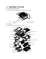
Page 6: ...kg 24 2 lbs 1 1 2 Components The equipment consists of the following major components ADF document tray ASSY Scanner top cover Scanner base Relay PCB Jam clear cover Rear cover Bottom plate Enclosure cover NCU PCB Main PCB Ink absorber box Power supply PCB Lower cover Purge unit Main chassis Auto sheet feeder ASF Main cover Control panel ASSY W 468 mm 18 4 including handset H 370 mm 14 6 D 467 mm ...

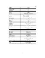
Page 7: ... Weight w o Carton 24 2 lbs 11 kg Color Gray 1495 Standby Mode No PC Fax Protocol Compliance N A Simultaneous Operation Yes Print Fax Print Scan Energy Star Compliant Yes Operating Environment Temperature Humidity 10 35 degrees Centigrade 20 to 80 Power Source 120 VAC 50 60 Hz Power Consumption Standby Peak Under 13 5W 40W On Off Switch No TELEPHONE Handset No One Touch Dial No Speed Dial Max 40 S...

Page 8: ...st card Photo Index card Manual Feed Slot N A Other Paper Type OHP Envelopes Sheet Weight Paper Cassette Manual Slot 64 120 g m2 17 32 lb N A Printer Driver Win95 98 98SE Me 2000Professinal NT4 0 MacOS 8 5 9 1 COPY Color Mono Color Mono Speed ppm 7 5 Mono Color Multi Copy Stack Yes Color or Via PC Multi Copy Sort Yes Color or Via PC Resolution dpi Max 1200x1200 color SCANNER Color Mono Color Mono ...

Page 9: ...3 1 lbs 15 kg Color Gray 1495 Operating Environment Temperature Humidity 10 35 degrees Centigrade 20 to 80 Power Source 240 VAC 50 60 Hz Power Consumption Standby Peak Under 13W 50W On Off Switch No TELEPHONE Handset N A One Touch Dial N A Speed Dial Max 100 Speaker Phone No Chain Dialing Yes Caller ID No Call Waiting Caller ID No Distinctive Ringing Yes Only UK Denmark Hold Mute Key No Hook Key T...

Page 10: ... OHP Envelopes Sheet Weight Paper Cassette Manual Slot 64 120 g m2 17 32 lb N A Printer Driver Win95 98 98SE Me 2000Professinal NT4 0 MacOS 8 5 8 5 1 8 6 9 0 9 04 9 1 COPY Color Mono Color Mono Speed ppm 7 4 Multi Copy Stack Yes Color or Via PC Multi Copy Sort Yes Color or Via PC Resolution dpi Max 1200x1200 SCANNER Color Mono Color Mono Resolution dpi Physical CCD 600x2400 Opt Resolution dpi Logi...

Page 11: ...CHAPTER 2 INSTALLATION ...

Page 12: ...APTER 2 INSTALLATION CONTENTS 2 1 INSTALLING THE UPDATE DATA TO THE FACSIMILE MACHINE 2 1 2 2 SETTING ID CODES TO FACSIMILE MACHINES 2 3 2 3 UPDATING HEAD PROPERTY INFO STORED IN THE FACSIMILE MACHINE 2 5 ...

Page 13: ...turned off 2 Make sure that the power cord of the facsimile machine is unplugged from a wall socket or other power source 3 Connect the parallel interface cable to the parallel port on the back of the machine and secure it with the lock wires 4 Connect the other end of the interface cable to the printer port of your PC and secure it with two screws 5 While pressing the 5 key on the machine s contr...

Page 14: ... above example type C from the command line and press the ENTER key Then type CD UPDATE and press the ENTER key 4 Check that your PC is connected with the facsimile machine correctly 5 To start the transfer utility transmitting the update data to the flash ROM of the facsimile machine type the following ICEN filename b Where filename is an update data file e g 5100x upd and 590xxxx upd Then press ...

Page 15: ...is turned off 2 Make sure that the power cord of the facsimile machine is unplugged from a wall socket or other power source 3 Connect the interface cable to the parallel interface port on the back of the facsimile machine and secure it with the lock wires 4 Connect the other end of the interface cable to the printer port of your PC and secure it with the two screws 5 While holding down the Menu k...

Page 16: ...ntenance mode refer to CHAPTER 5 Section 5 1 and then press the 1 key twice Subsection 5 3 6 The facsimile machine will print out a Configuration List At the right top of the list SER BROXXXXXXXXX is printed 4 Check that the character string entered in step 2 is printed in XXXXXXXXX If it is OK press the 9 key twice to exit from the maintenance mode If something other than that is printed in XXXXX...

Page 17: ...g a PC refer to CHAPTER 5 Subsection 5 3 14 Connecting the facsimile machine to your PC See the illustration on page 2 1 1 Make sure that your PC is turned off 2 Make sure that the power cord of the facsimile machine is unplugged from a wall socket or other power source 3 Connect the interface cable to the parallel interface port on the back of the facsimile machine and secure it with the lock wir...

Page 18: ...mode 3 To check whether the entered head property is correct make the machine enter the maintenance mode refer to CHAPTER 5 Section 5 1 and then press the 7 key twice The facsimile machine will print out the Equipment s Log On the line about 1 3 of full length of the log sheet below from the top the 12 digit code will be printed 4 Check that the character string entered in step 2 is printed in XXX...

Page 19: ...CHAPTER 3 THEORY OF OPERATION ...

Page 20: ...nk Jet Printing Mechanism 3 6 3 2 2 1 Paper pulling in registration feeding and ejecting mechanisms 3 6 3 2 2 2 Ink jet printing and capping mechanisms 3 8 3 2 2 3 Purging mechanism 3 11 3 2 2 4 Carriage drive mechanism 3 14 3 2 3 Sensors and Actuators 3 15 3 3 CONTROL ELECTRONICS 3 18 3 3 1 Configuration 3 18 ...

Page 21: ...ne Print data AC Control panel USB interface Scanner unit Paper feeding mechanism Power supply Ink jet printer unit Centronics parallel interface CCD unit CCD motor ADF unit ADF motor Ink jet print head unit Carriage motor Carriage ASSY Purge unit Host Paper feed motor ...

Page 22: ...ng mechanisms SCANNER MECHANISM ADF mechanism Document scanning mechanism INK JET PRINTING MECHANISM Paper pulling in registration feeding and ejecting mechanisms Ink jet printing and head capping mechanisms Purging mechanism Carriage drive mechanism SENSORS AND ACTUATORS ...

Page 23: ...3 3 SCANNER MECHANISM Ink jet printing and head capping mechanisms Purge mechanism Carriage drive mechanism Paper pulling in registration feeding and ejecting mechanisms INK JET PRINTING MECHANISM ...

Page 24: ... and document front and rear sensors The scanner unit consists of a scanner top cover CCD unit CCD drive mechanism CCD HP sensor and scanner base For details about the sensors refer to Subsection 3 2 3 Scanner base ADF document tray ASSY Document tray Document guide base Document ejection roller ADF motor Document feed roller Separation roller ASSY Scanner unit Scanner top cover CCD drive belt CCD...

Page 25: ... or put a bound book opened on the glass of the scanner top cover close the ADF document tray ASSY and start the scanning operation then the CCD drive mechanism will be driven The CCD motor built in the CCD unit rotates As illustrated below the CCD drive gear and idle pulley carry the CCD drive belt on the underside of the CCD unit so clockwise and counterclockwise rotations of the CCD motor move ...

Page 26: ...aper feed roller rotates in the backward direction to register the leading edge of the pulled in paper Next the paper feed motor rotates counterclockwise to rotate the paper feed roller in the forward direction The paper will advance through the paper path During the paper feeding operation no rotation is transmitted to the ASF roller because of the planetary gear system built in the ASF roller un...

Page 27: ...3 7 Gear 39 Gear 31MF Gear shaft 17 ASF roller unit Gear 25 ASF purge switching gear 23 Paper feed roller PF roller gear Paper feed motor ASF purge idle gear PF roller gear R ...

Page 28: ...nsors Paper ejection roller 1 Print head unit This machine uses drop on demand ink jet printing Each of the right and left print heads has an ink jet unit that has a pair of nozzle columns for two color inks A nozzle column consists of 75 nozzles 75 channels covered with piezoelectric ceramic PZT a manifold and filter As illustrated below the pair of nozzle columns is staggered Nozzle Layout viewe...

Page 29: ...g the ink to jet out through the nozzle The jetted out ink drop will be splashed and produce a dot on paper held by the platen As the carriage holding the print head unit travels at the printing speed the controller sends print command pulses to the piezoelectric actuator driver circuit embedded in the print head unit 2 Ink cartridges The machine uses four ink cartridges black cyan yellow and mage...

Page 30: ... to the right and moves the head cap holder provided on the purge unit to the right together In the head cap holder is a head cap unit which is supported with a lift lever The rightward movement of the head cap holder turns the lift lever and pushes up the head cap unit to the position where the head caps come into tight contact with the print heads This way the nozzles will be capped ...

Page 31: ... illustration below Accordingly the ASF purge switching gear 23 which was shifted to the left by the purge lever will move to the right by the switching gear spring so as to become disengaged from the gear 25 and engaged with the purge bevel gear A See the illustration given on the next page This engagement will transmit the motor rotation to the purge bevel gear B on the purge unit This way when ...

Page 32: ... purge switching gear 23 is engaged with purge bevel gear A When the motor rotation is transmitted to the purge unit its counterclockwise rotation will drive the purge cam and its clockwise rotation the pump switching unit when viewed from the output gear of the motor When the paper feed motor rotates counterclockwise When the paper feed motor rotates clockwise ...

Page 33: ...s out and locks the carriage to align ink jet units with the mating head caps during purge operation After purging but before cleaning with the head wiper it pops in to release the carriage When the power is off the carriage lock keeps the print heads pressed against the head caps 2 Purging If activated the pump draws out ink to purge air bubbles or dust from the inside of the head nozzles and cha...

Page 34: ...nd guided by the carriage rail is secured to the timing belt Clockwise and counterclockwise rotations of the carriage motor move the carriage to the right and left respectively On the back of the carriage is the carriage encoder which tells the control circuitry the current carriage position counted based on the carriage motor position by using the encoder strip attached to the main chassis ...

Page 35: ...er the document tray is closed Scanner open sensor which detects whether the scanner unit is closed Registration sensor which detects the leading and trailing edges of paper which allows the controller to determine the registration timing and check paper jam Paper width sensor which detects whether the paper width is A4 size or wider or narrower than A4 size CCD HP sensor which detects whether the...

Page 36: ...ch which detects whether the pump switching cam is in the home position These photosensors except the ink empty sensor that is a reflection type are a photointerrupter consisting of a light emitting diode and a light sensitive transistor Each of them has an actuator separately arranged as shown on the next page ...

Page 37: ...ear sensor CCD HP sensor CCD HP sensor plate Control panel PCB Scanner open sensor actuator Scanner open sensor Registration sensor actuator Pump switching cam HP switch Ink empty sensor Sensor support Relay PCB Paper width sensor Registration sensor Paper width sensor actuator Paper chute Purge cam HP switch Purge unit Location of Sensors and Actuators ...

Page 38: ...pin Other models AC line PC 3 pin 3 pin 2 pin Paper width sensor Main PCB EEPROM DC motor driver Stepping motor driver Engine GA SDRAM 8MB 2MB Main ASIC ROM 2MB MODEM Ink empty sensor Sensor support Registration sensor Paper chute Purge unit Purge cam HP switch Pump switching cam HP switch 12 pin 11 pin 9 pin 7 pin CCD unit CCD motor CCD HP sensor 4 pin 4 pin ADF motor Document sensor PCB Document...

Page 39: ...CHAPTER 4 DISASSEMBLY REASSEMBLY LUBRICATION AND ADJUSTMENT ...

Page 40: ...kness adjuster and pressure rollers 4 13 Upper ADF chute 4 15 4 1 4 ADF Components on the Lower ADF Chute 4 16 Document front and rear sensor actuators 4 16 Document sensor PCB 4 16 Document guide clips 4 17 Document ejection roller 4 17 Document pressure bar 4 18 Lower ADF chute pinch rollers and ADF motor 4 19 4 1 5 Document Tray Open Sensor and Document Stopper 4 21 4 1 6 Jam Clear Cover Rear C...

Page 41: ...Related Gears 4 49 4 1 19 Paper Pressure Holders 4 51 4 1 20 Paper Chute and Registration Sensor 4 52 4 1 21 Paper Ejection Roller Gear Ink Empty Sensor PCB Platen Star Wheel Support and Paper Ejection Roller 4 54 4 1 22 Paper Feed Motor and Paper Feed Roller 4 57 4 1 23 Encoder Strip and Carriage Motor 4 58 4 1 24 Carriage Rail Carriage ASSY and Purge Related Parts 4 60 4 1 25 Flushing Gutter and...

Page 42: ...y 6 When transporting PCBs be sure to wrap them in conductive sheets such as aluminum foil 7 Be sure to reinsert self tapping screws correctly if removed 8 Tighten screws to the torque values listed on the next page 9 When connecting or disconnecting cable connectors hold the connector bodies not the cables If the connector has a lock always slide the connector lock to unlock it 10 Before reassemb...

Page 43: ... 98 0 20 10 2 Guide plate Taptite cup B M3x8 3 0 69 0 10 7 1 CCD HP sensor plate Taptite cup B M3x8 1 0 69 0 10 7 1 Flat cable clamp Taptite cup B M3x8 2 0 69 0 10 7 1 ASF Taptite cup B M3x12 4 0 69 0 10 7 1 Edge cover Taptite cup B M3x12 2 0 69 0 10 7 1 Scanner link guides Taptite cup B M3x12 2 0 69 0 10 7 1 Relay PCB Taptite cup S M3x6 1 0 69 0 10 7 1 USB I F connector Screw pan M3x6 1 0 39 0 10...

Page 44: ...rew bind B tite M3x10 1 0 59 0 10 6 1 Platen plate R Taptite bind B M2 6x10 1 0 39 0 10 4 1 Platen plate L Taptite bind B M2 6x10 1 0 39 0 10 4 1 Paper feed motor Screw pan s p washer M3x6 2 0 78 0 10 8 1 Idle pulley holder Screw pan s p washer M3x8 1 0 78 0 10 8 1 Shoulder screw 1 0 78 0 10 8 1 Taptite cup S M3x6 1 0 98 0 10 10 1 Carriage motor Screw pan s p washer M3x6 2 0 78 0 10 8 1 Eccentric ...

Page 45: ...s when disassembling the machine except when removing the print head unit Telephone line cord Paper tray Paper wire extension How to Access the Object Component On the next page is a disassembly order flow which helps you access the object components To remove the purge unit for example first find it on the flow and learn its number in this case You need to remove parts numbered and so as to acces...

Page 46: ...is an ink empty sensor NOTE 9 On the carriage PCB are four ink cartridge sensors a carriage encoder and head thermister Print head unit 4 1 1 Document stopper Document tray Hinges Scanner unit with document tray Relay PCB cover Control panel ASSY Main cover Relay PCB NOTE 4 4 1 12 4 1 15 4 1 12 Scanner open lever Lever spring Scanner open sensor actuator Piezo ringer Document tray open sensor Edge...

Page 47: ...the print head unit with a new one replace also the ink absorber box and ink cartridges with new ones 1 Plug the power cord into a wall socket 2 Press the Ink key to place the machine in the ink replacement mode 3 Press the 2 key to choose 2 REPLACE INK 4 Press the Menu Set key The carriage automatically moves left to the ink replacement position 5 Unplug the power cord from the wall socket 6 Pull...

Page 48: ... head clamp spring Boss of the carriage NOTE Do not touch the printing ends nozzles of the print head unit or the ink orifices of the ink cartridges doing so will not only stain your hands with ink but result in an ink jet out failure Once you touch them clean them with a dedicated cleaning stick and liquid NOTE Be sure to put a head nozzle seal and filter seal on the print head unit as shown belo...

Page 49: ...n of arrow and pushing them up in the direction of arrow 10 Turn the head adjuster lever located on the right side of the carriage to position 1 11 To install a new or removed print head unit remove the head nozzle seal 12 Put the print head unit into the carriage with care for the dimple contact so that the electrical contact on the head PCB comes into uniform contact with that on the carriage PC...

Page 50: ...ttom right front corner of the carriage to the rear 18 Close the scanner unit 19 Plug the power cord into a wall socket The carriage automatically moves to the right hand home position 20 Follow the instructions shown on the LCD NOTE The machine enters a head cleaning cycle that takes approx 3 minutes for each ink cartridge 21 Update the head property information stored in the EEPROM of the main P...

Page 51: ...ect Wrong 2 Remove the document support 3 Release the two latches of the document guide base and slide it up straight along the guides NOTE Do not turn it to the left Doing so will break the groove sections of the document guide base Document guide base Groove Latches ADF document tray ASSY Guides Groove Document support Reassembling Notes When setting the ADF cover back into place fit its bottom ...

Page 52: ...cover 1 As illustrated below insert the tip of a flat screwdriver into the slot and lift up the right edge of the gear cover arrow and move the gear cover to the front arrow Front Gear cover Latch Latch Latch Upper ADF chute Left Flat screwdriver Rib Ribs ...

Page 53: ...roller ADF drive unit Rear ADF document tray ASSY Ribs of the bushings ADF drive unit Upper ADF chute Document feed roller shaft Separation roller shaft Spring plate When setting the separation roller take care not to apply force to the spring plate at an angle Separation roller Bushings S Separation roller ASSY Fitting the bushings into the cutouts provided in the ADF drive unit and setting the p...

Page 54: ...rce to the spring plate at an angle as illustrated on the previous page Reassembling Note After setting the rear end of the separation roller ASSY or document feed roller to the ADF drive unit fit its bushing into the cutout provided in the ADF drive unit with its rib facing up Then set the plastic retaining ring inside the upper ADF chute as illustrated on the previous page Separation rubber unit...

Page 55: ...er shaft press the latch to the right and take out the pressure rollers and their shaft Then remove their springs ADF thickness adjuster Taptite pan B M3x6 ADF thickness adjuster Upper ADF chute Rear Pressure rollers Pressure roller shaft Pressure roller springs Latches When setting the ADF thickness adjuster do not put the boss provided on the underside of the adjuster on the guide Wrong position...

Page 56: ...d of the upper ADF chute Latching the upper ADF chute Viewed from Y Y Taptite cup B M3x10 Rear Latches Upper ADF chute Document tray 4 1 2 3 Left Latches Latches Tabs Document tray Upper ADF chute Reassembling Note When latching the upper ADF chute first fit tabs 1 of the right end into the openings provided in the document tray then press latches 2 3 and 4 into place in this order as shown above ...

Page 57: ...Rear Document front sensor actuator Document rear sensor actuator Lower ADF chute Document sensor PCB 2 Take the document sensor harness out of the cable hooks then disconnect it from the document sensor PCB 3 Press the locking pawl to the front and take out the document sensor PCB Document sensor PCB Document sensor harness Lower ADF chute Rear Cable hooks Locking pawl Document rear sensor Docume...

Page 58: ...er shaft Document guide clip Lower ADF chute Document ejection roller 5 Remove the pawled bushing from the front end of the document ejection roller shaft by pulling its pawls outwards 6 Slide the rear bushing to the rear and then lift up the document ejection roller Pawled bushing Document ejection roller Rear bushing Lower ADF chute Rear Boss ADF drive unit ...

Page 59: ...SY 8 Pull either of the front and rear supports of the document pressure bar outwards and remove the document pressure bar The spring also comes off Document pressure bar Supports ADF document tray ASSY Document pressure bar Spring Wrong Correct Setting the spring Viewed from X Spring X Reassembling Note After setting the document pressure bar check in the direction of arrow X that the spring is i...

Page 60: ...m the lower ADF chute 13 Lift up the lower ADF chute in the direction of the arrow shown below taking care not to touch the anti static brush 14 Press the latch to the left and remove the pinch rollers and its shaft Grounding wire ADF drive unit When reinstalling the lower ADF chute turn the planet gear counterclockwise when viewed from the rear Planet gear Taptite cup B M3x10 ADF motor harness Gr...

Page 61: ...ssembling Note Before reinstalling the lower ADF chute to the document tray be sure to turn the planet gear on the ADF drive unit counterclockwise when viewed from the rear as illustrated on the previous page Reassembling Note For routing the ADF motor harness document sensor harness and grounding wire refer to Subsection 4 1 26 Harness routing A Secure the grounding wire at the angle shown on the...

Page 62: ...the document tray 3 Press the right and left latches of the document tray open sensor with the tip of a flat screwdriver as shown below and push it down Latches Document tray Document tray open sensor harness Document tray open sensor 4 Slightly open the document stopper and remove it while warping it Document tray Document stopper ...

Page 63: ...ver and remove it while warping it 2 Remove the two screws from the rear cover and take if off to the rear Rear cover Jam clear cover Taptite cup B M3x12 3 Slightly pull up the rear edge of the inner cover and pull it out to the rear Auto sheet feeder ASF Inner cover Lower cover ...

Page 64: ...g harnesses and flat cable from the relay PCB CCD flat cable Document tray open sensor harness Document sensor harness Panel harness ADF motor harness NOTE Handle the CCD flat cable with care Grounding wire From the ADF drive unit Rear Relay PCB CCD flat cable Document tray open sensor harness Document sensor harness Panel harness ADF motor harness Relay PCB Screw bind B tite M4x16 Grounding wire ...

Page 65: ...and lift up its rear edge to disengage it from the main cover in the direction of arrow Be careful with this boss provided for the scanner open sensor actuator Scanner link Panel harness CCD flat cable Harnesses Document tray open sensor harness document sensor harness ADF motor harness and grounding wire covered with the cable sheath Main cover Scanner unit Scanner link support Releasing the scan...

Page 66: ... sheath from the latch and move them to the front in the opening 8 Lift up the document tray 9 From the hinge base R remove the hinge arm as shown below Remove the three screws and release the hinge base R 10 From the hinge L that should be kept opened remove the three screws Hinge base R Document tray Hinge L Hinge arm Taptite cup B M3x10 Taptite cup B M3x10 ...

Page 67: ...ly procedure of the control panel ASSY and scanner unit refer to Subsections 4 1 8 and 4 1 9 respectively 15 Remove the three screw from the piezo ringer cap and take out the piezo ringer and its cap 16 Remove the lever spring Insert the tip of a flat screwdriver into slit s push up the lock and remove the scanner open lever in the direction of the arrow s Control panel ASSY Panel harness Scanner ...

Page 68: ... bound section through the cable guide so that the cable binder comes into contact with the cable guide as illustrated on page 4 25 Refer to Subsection 4 1 26 Harness routing A When putting the scanner unit on the scanner mount take special care not to bend wrinkle or scratch the CCD flat cable or not to break the boss of the main cover by the bottom of the scanner unit See the illustration given ...

Page 69: ...he reinforcement plate and FPC key FPC key Control panel LCD Taptite cup B M3x6 Control panel PCB Scanner open sensor Reinforcement plate 4 As shown below pull the lock arms outwards to release the LCD and pull the LCD flat cable gently Lock arm Rear Lock arm LCD Reassembling Notes Before reinstalling the LCD to the control panel wipe fingerprints or dust off the LCD surface and control panel wind...

Page 70: ...nit The disassembly job of the scanner unit should be done in a clean room to prevent dust or dirt from getting into the scanner unit 1 Remove the four screws from the scanner top cover 2 Separate the scanner top cover from the scanner base ...

Page 71: ...underside of the CCD unit NOTE Once removed the belt stopper will become unusable and new part will have to be put back in CCD drive belt CCD drive belt CCD unit turned upright Toothed side facing outwards Boss a Boss b Boss b Belt spring Belt clip Left front end of the CCD drive belt Right rear end of the CCD drive belt Scanner base CCD idle pulley CCD motor gear Underside of the CCD unit turned ...

Page 72: ...esive tape 7 Lift up the CCD rail together with the CCD unit from the scanner base then pull out the CCD rail NOTE When handling the CCD unit do not touch the CCD PCB or glasses but hold the hatched sections as shown on the next page CCD unit CCD rail CCD PCB CCD HP sensor Panel harness Double sided adhesive tape Scanner base CCD flat cable Double sided adhesive tape CCD flat cable attached to the...

Page 73: ...4 32 8 Remove the three screws and lift up the guide plate 9 Remove the screw from the CCD HP sensor plate ...

Page 74: ...w cover plates are covered with a protection sheet so remove the protection sheet before attaching When using a new CCD flat cable fold it and secure it to the scanner base with double sided adhesive tape and sponge R backed with adhesive tape as illustrated above Then attach it to the underside of the CCD unit with double sided adhesive tape When reassembling the components inside the scanner uni...

Page 75: ...ve the four screws from the ASF to release it Main cover ASF Taptite cup B M3x12 2 Pull out the separation pad ASSY 3 Remove the ASF film NOTE Once removed the ASF film will become unusable and a new part will have to be put back in ASF film ASF Separation pad ASSY ...

Page 76: ...en attaching a new ASF film to the ASF align its left right and rear edges with the recessed section as illustrated below taking care not to let the film override those edges of the recessed section ASF film 0 5 mm max ASF Separation pad ASSY Take care not to let the film override the edges of the recessed section Top view ...

Page 77: ...rom the main cover then remove the scanner links 3 From each of the scanner link guides remove screw y Pull up the rear end of each scanner link guide in the direction of arrow and slide the guide to the rear arrow Scanner link spring x Edge cover x Scanner link Scanner link spring Main cover Scanner link guides y Scanner link y x and y Taptite cup B M3x12 ...

Page 78: ...plate and then pull up the PCB plate 6 To remove the main PCB in the next subsection remove two screws d from the parallel I F connector Main 3 relay harness b Grounding wire From the ADF drive unit PCB plate d d c Lower cover Main 1 white leads 12 pin Main 2 red leads 11 pin Main 3 white leads 9 pin Relay harnesses Relay PCB cover Relay PCB a Relay PCB Main 1 relay harness Main 2 relay harness Gr...

Page 79: ... empty sensor harness Paper feed motor harness Carriage motor harness Purge switch harness Registration sensor harness Purge switch harness Main PCB Rear Paper width sensor Registration sensor harness Carriage motor harness Paper feed motor harness Ink empty sensor harness Main 2 relay harness Main 3 relay harness Head flat cable 2 Head flat cable 1 Main 1 relay harness ...

Page 80: ... ink absorber box unless it requires replacement When replacing it set a new one soon after the removal to prevent the machine from getting stained with drained ink NOTE If the print head unit is replaced with a new one replace also the ink absorber box with new one NOTE If the ink absorber box or the surrounding parts are stained with ink wipe them with a waste cloth Latch Bottom plate Taptite cu...

Page 81: ... Main 1 white leads 12 pin Main 3 white leads 9 pin Main 2 red leads 11 pin Relay harnesses Power supply harness Lower cover placed upside down FG plate L Main PCB Enclosure cover Latch b FG plate R Power supply PCB Power supply PCB Rubber bushing of the power cord Boss of the lower cover Grounding terminal x Reassembling Notes Be sure to route the power supply harness as illustrated above Route t...

Page 82: ...4 41 Setting up the main PCB after replacement Important NOTE Before starting the following procedure make sure that the print head unit is installed ...

Page 83: ...4 42 4 1 14 Enclosure Cover 1 While pulling up the FG plate R lift up the enclosure cover FG plate R Enclosure cover Lower cover ...

Page 84: ...rear hooks provided on the inside of the main cover 4 Lift up the main cover CAUTION After removing the main cover do not turn the machine upside down The main chassis may be warped or distorted so that the print quality could deteriorate Screw bind B tite M4x16 Main cover PCB plate c Grounding wire From the ADF drive unit Rear hook Cover retainer R Lower cover Media cover Cover retainer R Rear ho...

Page 85: ...When installing the main cover take care not to bring the tab of the ASF roller unit inside the main cover The tab should be fitted to the rear edge of the main cover as illustrated below Tab of the ASF roller unit Main cover ...

Page 86: ... frame supporter and lift it up 4 Remove two screws b one from the right side and the other from the rear side of the purge unit 5 Remove the drain tube from the tube guides and pull it out NOTE Cover the end of the drain tube with a waste cloth to prevent drained ink from leaking out and making stains on the machine 6 Pull the purge unit to the front in the direction of arrow Then while pulling t...

Page 87: ...ch from the purge unit by pulling the latches outwards respectively Purge switch harness Pump switching cam HP switch Blue lead Purge unit Drain tube Purge cam HP switch White lead Purge cam HP switch White lead Pump switching cam HP switch Blue lead Latches Viewed from the front Viewed from the rear Cable guide Rear 8 Remove the purge bevel gear A See the illustration given on the previous page R...

Page 88: ...he lower cover 2 Remove screw x from the lower end of FG plate R see the next page if you have not removed it on page 4 40 3 Remove screws y and z from the upper ends of FG plates R and L respectively then remove those plates Removing the FG plate L releases the head flat cables 4 Remove screw a from each of the chassis supporters 5 Unhook the two latches and lift up the main chassis NOTE If vibra...

Page 89: ...empty sensor harness Latch Lower cover Paper feed motor harness Ink empty sensor harness Shield film Shield film x Taptite cup B M3x12 y and z Taptite cup S M3x5 a Taptite cup B M3x12 Reassembling Notes When installing the main chassis to the lower cover make sure that the four vibration absorbers are fitted on the bottom ends of the main chassis After installing the main chassis be sure to route ...

Page 90: ... remove it to the rear 3 Remove the gear 31MF by pulling its pawls outwards The gear shaft 17 and bushing also come off NOTE Take care not to lose the bushing 4 Remove gear 39 and gear 25 from the main chassis Gear 39 Gear 31MF Bushing Gear shaft 17 ASF roller unit ASF roller ASSY ASF support Taptite cup S M3x6 Main chassis Gear 25 ...

Page 91: ... Roller Unit 1 Pull the pawl of the ASF gear 31 outwards and pull out the gear shaft 15 The ASF roller ASSY and the ASF gear 32 also come off 2 Remove the screw from the ASF roller ASSY Then it will be disassembled as shown below ...

Page 92: ...op end of the spring from the main chassis 2 Remove the paper pressure holders Main chassis Paper pressure holder R Paper pressure holders M Springs Paper pressure holder L Reassembling Notes When replacing films on the paper pressure holders with new ones attach them as illustrated below ...

Page 93: ...4 52 4 1 20 Paper Chute and Registration Sensor 1 Remove the screw from the rear of the paper chute and take it off from the main chassis Main chassis Paper chute Taptite cup S M3x6 ...

Page 94: ...4 53 2 Unhook the registration sensor 3 Unhook the actuator spring 4 Push the lock arm and slide the sensor actuator in the direction of arrows and ...

Page 95: ...e left end of the paper ejection roller 2 Remove the screw from the left side of the sensor support and take it off in the direction of the arrow Ink empty sensor PCB Paper ejection roller gear Paper ejection joint Taptite cup S M3x6 Sensor support Main chassis Support spring Left end of the paper ejection roller 3 Remove the screw from the ink empty sensor PCB ...

Page 96: ...screws from the platen and pull it out in the direction of the arrow NOTE Take care not to touch the flushing sponge that is impregnated with ink Shoulder screw Main chassis Platen Flushing sponge Screw bind B tite M3x10 ...

Page 97: ...ction roller by pulling its pawls outwards 8 Remove the paper ejection roller and bushing white 9 Remove the screw from each of the right and left platen plates Star wheel A Latches Star wheel A Platen plate L Flushing sponge Star wheel spring Star wheel B Star wheel spring Pawled bushing Paper ejection roller Platen Bushing white Platen plate R Latches Taptite bind B M2 6x10 Star wheel support St...

Page 98: ...hing R Paper feed roller PF spring PF bushing L PF roller gear Crescent ring PF idle gear Idle gear spring Screw pan s p washer M3x6 Paper feed motor Carriage ASF purge idle gear Color marking red or blue Retaining ring Reassembling Notes When replacing the paper feed roller check the color marking shown above made on the current roller and use a new roller having the same color marking When setti...

Page 99: ...ring c Idle pulley holder b a Pulley spring Strip guide Carriage Encoder strip Main chassis Main chassis Carriage motor pulley a Screw pan s p washer M3x8 b Shoulder screw c Taptite cup S M3x6 2 Move the carriage to the center of its travel 3 Loosen two screws a and c on the idle pulley holder See the above illustration 4 While pushing the idle pulley holder to the right remove the timing belt fro...

Page 100: ...ssis Reassembling Notes Pass the encoder strip through the strip guide provided on the back of the carriage so that the encoder strip will route as illustrated on the previous page and the marked end comes to the left Then hook the marked end on the spring hooked on the main chassis so that the mark points up ...

Page 101: ...nit or the ink orifices of the ink cartridges doing so will not only stain your hands with ink but result in an ink jet out failure Once you touch them clean them with a dedicated cleaning stick and liquid NOTE Be sure to put a head nozzle seal and filter seal on the print head unit shown on page 4 6 Leaving the print head unit without those seals will dry up its printing ends and filters resultin...

Page 102: ...not to lose the wavy washer 4 Pull out the carriage rail to the right NOTE The oil impregnated carriage felt will drop from the carriage 5 At the left side of the main chassis remove the screw from the eccentric bushing L if necessary Marking Screw pan s p washer M3x6DB Eccentric bushing R Wavy washer Carriage rail Eccentric bushing L Main chassis Carriage felt Carriage Eccentric bushing R ...

Page 103: ...esive tape From the front side unlatch the flat cable clamp to release the head flat cables 7 Remove the FFC clamp film from the left end of the main chassis 8 Remove tapes from the flat cable guide The carriage is now completely separated from the main chassis 9 Remove the timing belt from the back of the carriage ...

Page 104: ...e the PCB together with the sensor actuator support Unlatch the sensor actuator support from the carriage PCB 11 Press the right end of the purge shaft inwards and pull it out of the purge lever The purge lever spring also comes off 12 Remove the ASF purge switching gear 23 and its spring ...

Page 105: ...the eccentric bushing L Next fit the eccentric bushing R over the right end of the carriage rail temporarily set the bushing R to the right side of the main chassis with the screw align the bushing R with marking made on the main chassis and then tighten the screw firmly This alignment with markings is required for keeping the head platen gap properly When setting the head clamp springs refer to t...

Page 106: ... Actuator 1 Remove the screw and lift up the flushing gutter 2 Lightly push down the lock arm and remove the paper width sensor actuator in the direction of arrows and Lock arm Paper width sensor actuator Flushing gutter Lower cover Taptite cup B M3x12 ...

Page 107: ... tray Document tray Document tray open sensor harness Left Cable hooks Lower ADF chute Document sensor PCB Document sensor harness Cable hooks Harness routing B Relay PCB related harnesses Relay PCB Grounding wire From the ADF drive unit Document tray open sensor harness Document sensor harness ADF motor harness Rear Main 2 red leads 11 pin Main 1 white leads 12 pin Main 3 white leads 9 pin Relay ...

Page 108: ... Harness routing D Purge cam HP switch harness and pump switching cam HP switch harness on the lower cover CAUTION Be sure to insert the end of the drain tube into this hole provided in the lower cover that leads to the ink absorber box Purge unit Main chassis Drain tube Lower cover Leads of the purge cam HP switch white Leads of the pump switching cam HP switch blue Purge switch harness Be sure t...

Page 109: ...4 68 Harness routing E Head flat cables on the lower cover PCB plate Head flat cables Ferrite core Main PCB ...

Page 110: ... sesame sized pinch of grease 0 5 mm dia ball Sesame sized pinch of grease 2 mm dia ball Rice sized pinch of grease 3 mm dia ball Bean sized pinch of grease 4 mm dia ball Molykote PG662 Dow Corning Molykote EM 30LG or EM 30L Dow Corning EM0 1 Molykote EM 50LS Dow Corning Molykote HP 300 Dow Corning HP Conductive grease FLOIL 951P 32 Kanto Kasei Ltd 1 ADF thickness adjuster ...

Page 111: ...4 70 2 CCD rail in the scanner unit 3 Underside of the scanner unit HP HP HP Apply thin coat of grease to these three sections with a brush Scanner unit placed upside down ...

Page 112: ...4 71 4 ASF roller unit 5 Main cover Apply thin coat of grease to these two sections with a brush HP HP Main cover ...

Page 113: ...4 72 6 Paper ejection roller and platen Paper ejection roller Star wheel support Platen EM1 EM0 5 EM0 5 EM0 5 EM0 5 Star wheel A EM0 1 EM0 1 Apply to a total of 16 points on the star wheel support EM0 1 ...

Page 114: ...4 73 7 Paper ejection roller gear and PF roller gear 8 Paper feed roller and PF spring ...

Page 115: ...y a thin coat of grease to the right and left edges of the carriage rail with a brush Carriage rail Carriage P0 02 P0 02 10 Main chassis slideway of the carriage guide EM1 EM1 EM1 EM1 Main chassis Carriage guide ASF roller unit ...

Page 116: ...4 75 11 Purge shaft ...

Page 117: ...arallel port on the back of the machine and secure it with the lock wires Connect the other end of the interface cable to the printer port of your PC and secure it with the two screws 4 Plug the machine s power cord into a wall socket or other power source Then open the scanner unit 5 Turn on your PC 6 Make sure that the print head is secured to the carriage by the head clamp springs the ink cartr...

Page 118: ...control panel to place it in the ink replacement mode The carriage automatically moves to the ink replacement position 13 Open the scanner unit 14 Turn the head adjuster lever to the position indicated by the pattern number you recorded in step 11 NOTE Always turn the head adjuster lever in an ascending order If you want to set the head adjuster lever to position 3 for example turn it from 1 to 3 ...

Page 119: ...4 78 Head Positioning Test Pattern ...

Page 120: ...CHAPTER 5 MAINTENANCE MODE ...

Page 121: ...tional Check of Control Panel PCB 5 14 5 3 9 Sensor Operational Check 5 15 5 3 10 Fine Adjustment of Scanning Start End Position 5 16 5 3 11 CCD Scanner Area Setting 5 17 5 3 12 Setting the Sensing Reference Level of the Ink Empty Sensor 5 18 5 3 13 Alignment of Vertical Print Lines 5 19 5 3 14 Updating of Head Property Information 5 21 5 3 15 Initial Adjustment of PWM Value Aging of the Carriage ...

Page 122: ...nctions listed in Section 5 2 enter the corresponding 2 digit function code with the numerical keys on the control panel The details of each maintenance mode function are described in Section 5 3 NOTES Pressing the 9 key twice in the initial stage of the maintenance mode makes the equipment exit from the maintenance mode restoring it to the standby state Pressing the Stop key after entering only o...

Page 123: ...ne Adjustment of Scanning Start End Position 5 3 10 5 16 55 CCD Scanner Area Setting 5 3 11 5 17 57 Setting the Sensing Reference Level of the Ink Empty Sensor 5 3 12 5 18 65 Alignment of Vertical Print Lines 5 3 13 5 19 68 Updating of Head Property Information 5 3 14 5 21 69 Initial Adjustment of PWM Value Aging of the carriage 5 3 15 5 22 74 EEPROM Customizing 5 3 16 5 23 80 Display of the Equip...

Page 124: ...ible selectors which are shaded in the firmware switch tables in Appendix 2 The service personnel should instruct end users to follow the procedure given below 1 American models Press the Menu and Receive Mode keys in this order European models Press the Menu and Tel R keys in this order The LCD clears the current display NOTE The Receive Mode or Tel R key is disabled during standby for redialing ...

Page 125: ...n One touch dialing Speed dialing Group dialing All of these will be initialized These will not be initialized EEPROM customizing code 4 digit This will not be initialized Note that the first digit of the 4 digit code will be initialized to 0 If the code is 1001 for example it will be initialized to 0001 NOTE you replace the main PCB with one used for other facsimile equipment carry out this proce...

Page 126: ...the following a PWM value for controlling the lower limit of the A D converter reference voltage 1 byte b Max allowable value of a above 1 byte c Voltage divider ON OFF level for red image 1 byte d Voltage divider ON OFF level for green image 1 byte e Voltage divider ON OFF level for blue image 1 byte f Voltage divider ON OFF level for monochrome image 1 byte g Compensation data for background col...

Page 127: ...5 6 Scanning Compensation Data List ...

Page 128: ... station for repair then you should instruct him her to carry out this procedure if possible before packing and transporting the machine For the user access to the maintenance mode refer to page 5 3 Operating Procedure 1 Press the 0 and 6 keys in this order in the initial stage of the maintenance mode The CCD unit will move to the right end of its travel during which the MAINTENANCE 0 will appear ...

Page 129: ...llowable up to the ADF capacity The DOC READY will appear on the LCD 2 Press the 0 and 8 keys in this order While counting the documents the equipment feeds them in and out displaying the current count on the LCD as shown below Current count 1st page in this example 3 After counting all documents the equipment shows the final count To return the equipment to the initial stage of the maintenance mo...

Page 130: ... function prints out test pattern 1 to allow the service personnel to check for record data missing or print quality Operating Procedure Press the 0 and 9 keys in this order in the initial stage of the maintenance mode The figure below shows test pattern 1 Test Pattern 1 ...

Page 131: ...mode setting WSW04 TRANSFER facility setting WSW05 1st dial tone and busy tone detection WSW06 Pause key setting and 2nd dial tone detection WSW07 Dial tone setting 1 WSW08 Dial tone setting 2 WSW09 Protocol definition 1 WSW10 Protocol definition 2 WSW11 Busy tone setting WSW12 Signal detection condition setting WSW13 Modem setting WSW14 AUTO ANS facility setting WSW15 REDIAL facility setting WSW1...

Page 132: ...elector 8 WSWXX 0 0 0 0 0 0 0 0 3 Use the right and left arrow keys to move the cursor to the selector position to be modified 4 Enter the desired number using the 0 and 1 keys 5 Press the Set key This operation saves the newly entered selector values onto the EEPROM and readies the equipment for accepting a firmware switch number 6 Repeat steps 2 through 5 until the modification for the desired f...

Page 133: ...e switches Operating Procedure 1 Press the 1 key twice in the initial stage of the maintenance mode The PRINTING will appear on the LCD 2 The equipment prints out the configuration list as shown in the figure below 3 Upon completion of printing the equipment returns to the initial stage of the maintenance mode Configuration List ...

Page 134: ...n this order in the initial stage of the maintenance mode The LCD shows the screen given at right 2 Press the Black Fax Start key Each time you press the Black Fax Start key the LCD cycles through the displays shown at right 3 Press the Stop key in any process of the above display cycle The equipment beeps for one second and returns to the initial stage of the maintenance mode ...

Page 135: ...cimal notation each time a key or button is pressed Check that the displayed number is correct by referring to the illustration below If a key or button is pressed out of order the equipment beeps and displays the INVALID OPERATE on the LCD To return to the status ready to accept key button entry for operational check press the Stop key 3 After the last number key or button is pressed the equipmen...

Page 136: ...d DR Document rear sensor No document detected DC Document tray open sensor Document tray closed FH CCD HP sensor CCD unit placed in the home position CS Cassette sensor Not applicable to the MFC5100C MFC590 CV Scanner open sensor Scanner unit closed RS Registration sensor No recording paper detected PW Paper width sensor No paper detected P1 Purge cam HP switch Purge cam placed in the home positi...

Page 137: ...pears You may adjust the correction value to 11 levels from 5 to 5 mm 3 To increase the correction value press the left arrow key to decrease it press the right arrow key If you press the Stop key the equipment returns to the initial stage of the maintenance mode without making change of the correction value 4 Press the Set key The ACCEPTED appears on the LCD After one second the equipment returns...

Page 138: ...itial stage of the maintenance mode The SCANNER AREA SET will appear on the LCD The equipment checks and sets the area to be scanned If no error is noted the equipment returns to the initial stage of the maintenance mode If any error is noted the SCANNER ERROR will appear on the LCD To return the equipment to the initial stage of the maintenance mode press the Stop key ...

Page 139: ... completion of the setting procedure store the cartridge in the container Foam empty cartridge 1 Press the 5 and 7 keys in this order in the initial stage of the maintenance mode 2 Open the scanner unit The carriage automatically moves left to the ink replacement position 3 Remove the yellow ink cartridge The LCD shows SET F EMP CART NOTE When this message is displayed do not load or unload any ot...

Page 140: ...i and 1200 dpi If the vertical alignment is ON No 5 line each in the 600 dpi and 1200 dpi printouts shows vertically aligned lines as given on the next page The LCD shows the 600DPI NO 1 9 2 Check the printed vertical alignment check patterns for the 600 dpi and find which number line shows full alignment If the line is other than No 5 enter that line number by using the numerical keys The LCD sho...

Page 141: ...5 20 Vertical Alignment Check Pattern ...

Page 142: ...the initial stage of the maintenance mode 2 Press the 2 5 8 0 keys in this order The facsimile machine shows the current head property information 13 digit code e g 45352DABB485F stored in the EEPROM on the LCD and becomes ready to accept entry 3 Check the head property code printed on the bar code label attached to the print head unit Out of the 13 digit property code enclosed with asterisks e g ...

Page 143: ...or after completion of the aging Operating Procedure 1 Press the 6 and 9 keys in this order in the initial stage of the maintenance mode The equipment starts aging the carriage showing the CR AGING on the LCD After writing the initial value of the PWM onto the EEPROM and checking the head drive voltage level the equipment automatically returns to the initial stage of the maintenance mode If any er...

Page 144: ...ase of MFC5100C U S A versions appears 2 Enter the desired customizing code e g 2002 in the case of MFC5100C Canadian versions NOTE To enter letters A through F press the 1 through 6 keys while holding down the key respectively The newly entered code appears NOTE If a wrong 4 digit code is entered the equipment will malfunction 3 Press the Black Fax Start key The equipment saves the setting and re...

Page 145: ... been printed as an output device of the connected PC 7 Copy page count indicating how many copies have been made 8 FAX page count indicating how many received FAX pages have been printed 9 Purge count indicating how many times the purge operation has been carried out 10 Wiper count indicating how many times the wiper operation has been carried out 11 Ink cartridge change count indicating how many...

Page 146: ... the transmission log of the user s equipment at a remote location and use it for analyzing problems arising in the user s equipment Operating Procedure 1 If the user s equipment has a transmission related problem call the user s equipment at a remote location from your equipment 2 If the line is connected have the user perform the following 1 American models Press the Menu Receive Mode and 0 keys...

Page 147: ...lock mode so as not to exit from the mode NOTE Carrying out this procedure will lose passwords previously entered but retain FAX messages received in the Pin TX lock mode Operating Procedure 1 When the PIN TX LOCK is displayed on the LCD press the Menu and keys at the same time Within two seconds start to press the 2 7 9 0 and 0 keys The Pin TX lock mode will be canceled and the equipment returns ...

Page 148: ...CHAPTER 6 ERROR INDICATION AND TROUBLESHOOTING ...

Page 149: ...OR X X message 6 4 6 1 2 Communications Errors 6 8 6 2 TROUBLESHOOTING 6 15 6 2 1 Introduction 6 15 6 2 2 Precautions 6 15 6 2 3 Checking prior to Troubleshooting 6 15 6 2 4 Troubleshooting Procedures 6 17 1 Control panel related 6 17 2 Telephone related 6 17 3 Communications related 6 18 4 Paper document feeding related 6 18 5 Print image related 6 19 6 PC driven printing 6 22 ...

Page 150: ...he equipment enter the maintenance mode and then press the 8 and 2 keys Following the MACHINE ERROR one of the error codes listed in 2 will appear on the LCD 1 Error messages on the LCD Messages on the LCD Probable Cause CHECK CARTRIDGE Open cover then reinstall ink cartridge These messages appear alternately Any of the ink cartridges is not loaded CHECK DOCUMENT CHECK ORIGINAL Remove documents th...

Page 151: ...ges appear alternately The registration sensor detects no recording paper loaded in the auto sheet feeder ASF COVER OPEN PLS CLOSE COVER These messages appear alternately The scanner open sensor detects that the scanner unit is not closed DOC COVER OPEN Remove document then close cover These messages appear alternately The document tray is not closed HIGH TEMPERATURE COOL DOWN ROOM These messages ...

Page 152: ...LS OPEN COVER To display the relating detailed error code use maintenance mode function code 82 Refer to CHAPTER 5 Subsection 5 3 18 If this message appears open and close the scanner unit The message may disappear if opening closing the scanner unit removes the error If the error persists the MACHINE ERROR X X will appear instead of this message SCAN LAMP WARMUP After the fluorescent lamp in the ...

Page 153: ...yan ink has run out 29 The magenta ink has run out Ink cartridges Cartridge PCB Head flat cables Main PCB Ink empty sensor 2A No black ink cartridge is loaded Load the ink cartridge 2B No yellow ink cartridge is loaded Load the ink cartridge 2C No cyan ink cartridge is loaded Load the ink cartridge 2D No magenta ink cartridge is loaded Load the ink cartridge 3 Carriage travel error Carriage ASSY E...

Page 154: ...en after the purge cam has been driven by the specified number of pulses 52 The pump switching cam HP switch does not come ON even after the switching cam has been driven by the specified number of pulses 53 The pump switching cam HP switch does not go OFF even after the switching cam has been driven by the specified number of pulses Purge unit Purge related gears on the main chassis Purge bevel g...

Page 155: ... rear sensor Document front sensor actuator Document rear sensor actuator Control panel PCB Document sensor PCB Document feed roller ADF motor Main PCB A4 50 or more faulty of white level data CCD unit Main PCB A7 One line feeding timeout A8 One line scanning timeout AA The document tray is not closed Remove the document and close the document tray AC Less than 50 faulty of white level data CCD un...

Page 156: ...ure bar BD Black level data error CCD unit Main PCB BE Scan starting edge detection error CCD unit CCD harness Main PCB Black markings on the white level reference film inside the scanner top cover D Modem error Main PCB E4 Out of recording paper ASF Registration sensor actuator Document feed roller Main PCB E6 Write error in EEPROM Main PCB E8 Data scanning error during transmission EA Document r...

Page 157: ...tions error occurs the facsimile equipment emits an audible alarm intermittent beeping for approximately 4 seconds displays the corresponding error message and prints out the transmission verification report if the equipment is in sending operation ...

Page 158: ... dialing 17 07 No response from the calling station in receiving Available in German versions only 2 Command reception Code 1 Code 2 Causes 20 01 Unable to detect a flag field 20 02 Carrier was OFF for 200 ms or longer 20 03 Abort detected 1 in succession for 7 bits or more 20 04 Overrun detected 20 05 A frame for 3 seconds or more received 20 06 CRC error in answerback 20 07 Undefined command rec...

Page 159: ... its password switch OFF 32 11 Remote terminal not equipped with or not ready for confidential mailbox function 32 12 Remote terminal not equipped with or not ready for relay broadcasting function 32 13 No confidential mail in the remote terminal 32 14 The available memory space of the remote terminal is less than that required for reception of the confidential or relay broad casting instruction 3...

Page 160: ...le not ready 40 07 No document to send when polled 40 10 Nation code or manufacturer code not coincident 40 13 Polled by any other manufacturers terminal while waiting for secure polling 40 17 Invalid resolution selected 40 20 Invalid full color mode requested 5 Command reception checking the NSF and DIS after transmission of NSS and DCS Code 1 Code 2 Causes 50 01 Vertical resolution capability ch...

Page 161: ...sword plus lower 4 digits of telephone number not coincident 63 02 Password not coincident 63 03 Polling ID not coincident 7 DCN reception Code 1 Code 2 Causes 74 DCN received 8 TCF transmission reception Code 1 Code 2 Causes 80 01 Fallback impossible ...

Page 162: ... during operation except receiving into memory A0 13 Decoding error continued on 500 lines A0 14 Decoding error continued for 10 seconds A0 15 Time out 5 seconds or more for one line transmission A0 16 RTC not found and carrier OFF signal detected for 6 seconds A0 17 RTC found but no command detected for 60 seconds A0 18 Receive buffer full during receiving into memory A0 19 No video data to be se...

Page 163: ...ven during turn around transmission due to call reservation B0 04 PC interface error 12 Maintenance mode Code 1 Code 2 Causes E0 01 Failed to detect 1300 Hz signal in burn in operation E0 02 Failed to detect PB signals in burn in operation 13 Equipment error Code 1 Code 2 Causes FF X X Equipment error For X X refer to Subsection 6 1 1 2 ...

Page 164: ...he PCBs touch a metal portion of the machine to discharge static electricity charged in your body When repairing the PCBs handle them with extra care After repairing the defective section be sure to check again if the repaired section works correctly Also record the troubleshooting procedure so that it would be of use for future trouble occurrence 6 2 3 Checking prior to Troubleshooting Prior to p...

Page 165: ...tridges 1 Check that all of four ink cartridges are loaded Print head 1 Check that the print head is installed on the carriage correctly Check the dimple contact between the print head PCB and the carriage PCB 2 Repeat the head purging operation several times 3 Clean the print surface of the print head unit Refer to page 6 23 ...

Page 166: ... PCB FPC key Main PCB 2 Telephone related Trouble Check 1 No phone call can be made FPC key Control panel PCB NCU PCB Main PCB 2 Speed dialing or one touch dialing will not work Ordinary dialing function other than the speed and one touch dialing If it works normally check the main PCB if not refer to item 1 above 3 Dial does not switch between tone and pulse Main PCB 4 Telephone does not ring Rin...

Page 167: ...Subsection 5 3 9 Document front sensor actuator and document rear sensor actuator Main PCB Relay PCB 2 Document not fed ADF and its related sections ADF motor and its harness Document feed rollers and their related gears Main PCB Relay PCB 3 Document double feeding ADF parts 4 Document jam ADF motor Relay PCB 5 Recording paper not fed ADF related gears Main PCB Relay PCB 6 Recording paper jam Pape...

Page 168: ...n out of ink replace them Check the dimple contact between each of the print head PCB and the mating carriage PCB Clean it if contaminated If the problem persists replace the carriage ASSY Check the connection of the head flat cables on the main PCB If either of those cables is broken or damaged replace it Replace the main PCB Clean the head caps and wiper of the purge unit with a Rubycel stick Fo...

Page 169: ...he printer side For each of the four ink jet units perform the head purging operation several times to remove dust or air bubbles from its nozzles If the problem persists replace the print head unit Check the paper feed related rollers Replace the main PCB and power supply PCB 6 Black or blurred vertical stripes At the scanner Check the following components CCD unit Scanner glass At the printer si...

Page 170: ...power supply PCB Check that the eccentric bushings R and L are aligned with markings made on the main chassis to adjust the head platen gap 9 Random missing dots At the printer For each of the four ink jet units perform the head purging operation several times to remove dust or air bubbles from its nozzles Check the ink cartridges If any cartridges have run out of ink replace them Check the dimple...

Page 171: ...with a Rubycel stick For the cleaning procedure refer to Cleaning the purge unit given on the next page 11 Stained leading edge of recording paper At the printer Clean the nozzle ends of the ink jet units Check that the eccentric bushings R and L are aligned with markings made on the main chassis to adjust the head platen gap 6 PC driven printing Trouble Action to be taken 1 PC driven printing is ...

Page 172: ...used one for any other purge units NOTE During the cleaning jobs take care not to touch the head caps or wiper directly by hand or scratch their surfaces Do not remove them from the head cap holder Purge unit Head wiper Rubycel stick Head caps Cleaning the print head unit 1 Remove the print head unit from the carriage Refer to CHAPTER 4 Section 4 1 1 2 Soak a Rubycel stick in Glycerol cleaner 3 Cl...

Page 173: ...MFC5100C MFC590 Appendix 1 EEPROM Customizing Codes ...

Page 174: ...B001 in the case of MFC5100C U S A versions appears 3 Enter the desired customizing code e g 2002 in the case of MFC5100C Canadian version NOTE To enter letters A through F press the 1 through 6 keys while holding down the key respectively The newly entered code appears NOTE If a wrong 4 digit code is entered the equipment will malfunction 4 Press the Black Fax Start key The equipment saves the se...

Page 175: ...EALAND 2027 2 MFC590 Model Versions MFC590 GERMANY 2003 U K 2004 FRANCE 2005 BELGIUM 2008 NETHERLANDS 2009 SWITZERLAND 2010 IRELAND 2004 DENMARK 2057 AUSTRIA 2003 SPAIN 2015 ITALY 2016 SOUTH AFRICA 2004 EURO GENERIC 2054 PAN NORDIC 2057 To enter letters A through F press the 1 through 6 keys while holding down the key respectively ...

Page 176: ...MFC5100C MFC590 Appendix 2 Firmware Switches WSW ...

Page 177: ...de setting 23 WSW21 TAD setting 1 24 WSW22 ECM and copy resolution setting 24 WSW23 Communications setting 25 WSW24 TAD setting 2 26 WSW25 TAD setting 3 26 WSW26 Function setting 4 27 WSW27 Function setting 5 28 WSW28 Function setting 6 29 WSW29 Function setting 7 30 WSW30 Not used 30 WSW31 Function setting 9 31 WSW32 Function setting 10 32 WSW33 Function setting 11 33 WSW34 Function setting 12 34...

Page 178: ...mode pulse DP or tone PB dialing 0 PB 1 DP Selectors 1 and 2 Dial pulse generation mode These selectors set the number of pulses to be generated in pulse dialing N Dialing N generates N pulses Dialing 0 generates 10 pulses N 1 Dialing N generates N 1 pulses 10 N Dialing N generates 10 N pulses Selectors 3 and 4 Break time length in pulse dialing These selectors set the break time length in pulse d...

Page 179: ...ssion time length No 1 2 0 0 70 ms 0 1 80 ms 1 0 90 ms 1 1 100 ms 3 4 Min pause in tone dialing No 3 4 0 0 70 ms 0 1 80 ms 1 0 90 ms 1 1 140 ms 5 8 Attenuator for pseudo ring backtone to the line selectable in the range of 0 15 dB 0 0 dB 1 8 dB 0 0 dB 1 4 dB 0 0 dB 1 2 dB 0 0 dB 1 1 dB Selectors 1 through 4 Tone signal transmission time length and Min pause in tone dialing These selectors set the ...

Page 180: ...nd 7 are not applicable where no PABX is installed Selectors 1 and 5 CNG detection when sharing a modular wall socket with a telephone These selectors determine whether or not the equipment detects a CNG signal when a line is connected to a telephone sharing a modular wall socket with the equipment Upon detection of CNG signals by the number of cycles specified by these selectors the equipment int...

Page 181: ...e length for earth function No 5 6 0 0 200 ms 0 1 300 ms 1 0 500 ms 1 1 700 ms 7 8 Break time length for flash function No 7 8 0 0 80 ms 0 1 110 ms 1 0 250 ms 1 1 500 ms NOTE Selectors 1 and 5 through 8 are not applicable in those countries where no transfer facility is supported Selector 1 Earth function in transfer facility This selector determines whether or not the earth function is added to t...

Page 182: ...to the PSTN Setting all of these selectors to 1 activates the dial tone detection function so that the equipment starts dialing upon detection of a dial tone when a line is connected However in those countries which support no dial tone detection function e g in the U S A setting these selectors to 1 makes the equipment start dialing after a WAIT of 3 5 seconds For the detecting conditions of the ...

Page 183: ...isconnect the line Setting selectors 5 and 6 to 0 and 1 respectively makes the equipment detect a busy tone only after dialing and disconnect the line Setting both of selectors 5 and 6 to 1 makes the equipment detect a busy tone before and after dialing and then disconnect the line Selector 7 Busy tone detection in automatic receiving mode This selector determines whether or not the equipment auto...

Page 184: ... in pulse dialing DP system 1 0 1 2nd dial tone detection 1 1 1 both in DP and push button PB dialing system 4 6 Detection of international tone No 4 5 6 0 0 0 50 ms 0 0 1 210 ms 0 1 0 500 ms 0 1 1 800 ms 1 0 0 900 ms 1 0 1 1 5 sec 1 1 0 2 0 sec 1 1 1 2 5 sec 7 No of 2nd dial tone detection times 0 Once 1 Twice 8 2nd dial tone interrupt detecting time 0 30 ms 1 50 ms NOTE Selectors 4 through 8 are...

Page 185: ...AIT of 3 5 seconds When these selectors are set to 1 1 1 If you press the Pause key the equipment will first wait for the 2nd dial tone to be sent via the communications line regardless of pulse dialing or tone dialing After that pressing the Pause key will cause the equipment to insert a WAIT of 3 5 seconds In those countries where no dial tone detection function is supported setting these select...

Page 186: ...NOTE Selector 3 is not applicable to those models having no loop current detection function Selectors 1 and 2 Frequency band range These selectors set the frequency band for the 1st dial tone and the busy tone before dialing to be detected This setting is effective only when selectors 1 through 3 of WSW05 are set to 1 1 1 Selector 3 Line current detection This selector determines whether or not th...

Page 187: ... 0 1 36 dBm 1 1 0 39 dBm 1 1 1 42 dBm NOTE The WSW08 is not applicable in those countries where no dial tone detection is supported e g U S A Selectors 1 through 3 1st dial tone detection time length Upon detection of the 1st dial tone for the time length set by these selectors the equipment starts dialing This setting is effective only when selectors 1 through 3 of WSW05 are set to 1 1 1 Selector...

Page 188: ...de a message into 64 octet frames Remarks The error correction mode ECM is a facsimile transmission manner in which the equipment divides a message into frames for transmission so that if any data error occurs on the transmission line the equipment retransmits only those frames containing the error data Selector 2 Use of non standard commands If this selector is set to 0 the equipment may use non ...

Page 189: ...ML ON This selector sets the time length from when the equipment transmits the last dial digit until the CML relay comes on Selector 3 Time length from CML ON to CNG transmission This selector sets the time length until the equipment transmits a CNG after it turns on the CML relay Selector 4 Time length from CML ON to CED transmission This selector sets the time length until the equipment transmit...

Page 190: ... 1 175 440 175 440 ms 6 1 100 1000 ms 17 660 ms 7 1 110 410 320 550 ms 8 ON OFF time length ranges More than one setting allowed 1 100 660 100 660 ms NOTE WSW11 is not applicable in those countries where no busy tone detection is supported NOTE The setting of WSW11 is effective only when selectors 5 and 6 of WSW05 are set to 0 1 or 1 1 Busy tone detection Selectors 1 and 2 Frequency band range The...

Page 191: ...s 1 through 4 Min and max OFF time length of calling signal Ci If the equipment detects the OFF state of calling signal Ci for a time length which is greater than the value set by selectors 1 and 2 and less than the value set by selectors 3 and 4 it interprets the Ci signal as OFF Selectors 5 and 6 Detecting time setting These selectors set the time length required to make the equipment acknowledg...

Page 192: ...als on a line Attenuation in the high band frequency is greater than in the low band frequency Set these selectors according to the distance from the telephone switchboard to the facsimile equipment Selectors 3 and 4 Reception level These selectors set the optimum receive signal level Selectors 5 through 8 Modem attenuator These selectors are used to adjust the transmitting level of the modem when...

Page 193: ...times 1 0 1 0 2 to 5 times 1 0 1 1 2 to 6 times 1 1 0 0 1 to 10 times 1 1 0 1 2 to 10 times 1 1 1 0 3 to 5 times 1 1 1 1 4 to 10 times Selectors 1 through 4 Frequency band selection These selectors are used to select the frequency band of calling signals for activating the AUTO ANS facility In the French versions if the user sets the PBX to OFF from the control panel the setting made by selectors ...

Page 194: ...ponse sent from the called terminal 0 Redialing 1 No redialing 8 Not used Selectors 1 through 6 Selection of redial interval and No of redialings The equipment redials by the number of times set by selectors 3 through 6 at intervals set by selectors 1 and 2 Selector 7 Redialing for no response sent from the called terminal This selector determines whether or not the equipment redials if no G3 comm...

Page 195: ...CITT superfine recommendation If this selector is set to 1 the equipment communicates in ITU T CCITT recommended superfine mode 15 4 lines mm If it is set to 0 it communicates in native superfine mode Selector 7 Max document length limitation This selector is used to select the maximum length of a document to be sent Selector 8 Stop key pressed during reception If this selector is set to 1 pressin...

Page 196: ...s 1 and 2 Off hook alarm These selectors activate or deactivate the alarm function which sounds an alarm when the communication is completed with the handset being off the hook Selector 5 Calendar clock type If this selector is set to 0 USA the MM DD YY hh mm format applies if it is set to 1 Europe the DD MM YY hh mm format applies DD is the day MM is the month YY is the last two digits of the yea...

Page 197: ...lectors 2 and 3 Detection enabled time for CNG and no tone After the line is connected via the external telephone or by picking up the handset of the facsimile equipment the equipment can detect a CNG signal or no tone for the time length specified by these selectors The setting specified by these selectors becomes effective only when selector 8 of WSW20 is set to 1 Selector 6 Registration of stat...

Page 198: ...lectors 1 through 3 the equipment attempts to establish the transmission link via the MODEM If the establishment fails the equipment automatically steps down to the next lowest speed and attempts to establish the transmission link again The equipment repeats this sequence while stepping down the transmission speed to the last choice specified by selectors 4 through 6 If the MODEM always falls back...

Page 199: ...s According to the communications error state select the signal specifications Setting selector 2 to 1 allows the equipment to use 1100 Hz CED signal instead of 2100 Hz in receiving operation This prevents malfunctions resulting from echoes since the 1100 Hz signal does not disable the echo suppressor ES while the 2100 Hz signal does Setting selector 3 to 1 allows the equipment to ignore a DIS sig...

Page 200: ...le TCF bit error rate Only at 4800 bps 0 0 1 8 0 0 1 4 0 0 1 2 0 0 1 1 ECM Error correction mode NOTE Selector 3 is applicable to the American versions only NOTE Selectors 5 through 8 are applicable to the Chinese Taiwanese and Asian versions only Selector 3 Call Waiting Caller ID Setting this selector to 0 allows the user to decide whether or not to interrupt the current call when a new call come...

Page 201: ...cted If it is set to 1 the called station starts counting zeros upon detection of 10 ms successive zeros 50 ms after the head of a series of zeros is detected In this case if the detection of 10 ms successive zeros is too late the data counting period will become less than 1 0 second making the called station judge the line condition unacceptable Selectors 2 and 3 Allowable training error rate The...

Page 202: ...e an OGM facility the settings made by these selectors also apply to the length of time from CML ON up to the start of OGM transmission WSW25 TAD setting 3 Selector No Function Setting and Specifications 1 4 Not used 5 7 Pause between paging number and PIN No 5 6 7 0 0 0 2 sec 0 0 1 4 sec 0 1 0 6 sec 0 1 1 8 sec 1 0 0 10 sec 1 0 1 12 sec 1 1 0 14 sec 1 1 1 16 sec 8 Not used NOTE Selectors 5 throug...

Page 203: ...mory in in memory message transmission If this selector is set to 0 the facsimile equipment waits for document reading into the memory to complete and then starts dialing This enables the equipment to list the total number of pages in the header of the facsimile message Selectors 4 and 5 No of CNG cycles to be detected The equipment interprets a CNG as an effective signal if it detects a CNG signa...

Page 204: ...cable only to the U S A versions Selector 2 Ringer OFF setting This selector determines whether or not the ringer can be set to OFF Selector 4 Detection of distinctive ringing pattern If this selector is set to 1 the equipment detects only the number of rings if it is set to 0 the equipment detects the number of rings and the ringing time length to compare the detected ringing pattern with the reg...

Page 205: ... 0 dB 1 0 1 1 dB 1 1 0 2 dB 1 1 1 3 dB 4 6 Transmission level of DTMF low band frequency signal No 4 5 6 0 0 0 0 dB 0 0 1 1 dB 0 1 0 2 dB 0 1 1 3 dB 1 0 0 0 dB 1 0 1 1 dB 1 1 0 2 dB 1 1 1 3 dB 7 8 Not used Selectors 1 through 6 Transmission level of DTMF high low band frequency signal These selectors are intended for the manufacturer who tests the equipment for the Standard Never access them ...

Page 206: ... becomes full 0 No 1 Yes NOTE Selectors 7 and 8 are applicable only to the European versions Selector 8 Prompt beep for activity report This selector determines whether or not the equipment will beep if the memory area for the activity report becomes full for prompting you to print out the report Printing it out will clear the memory area WSW30 Selector No Function Setting and Specifications 1 8 N...

Page 207: ...ied if the automatic reduction function fails to record one page data sent from the calling station in a single page of the current recording paper If it is set to 0 the equipment records one page data at full size 100 without reduction if it is set to 1 the equipment records it at 70 size Selector 5 Minimum short OFF duration in distinctive ringing The ringer pattern consists of short and long ri...

Page 208: ... Default contrast No 7 8 0 X Automatic 1 0 Super light 1 1 Super dark Selectors 5 and 6 Default resolution These selectors set the default resolution which applies when the equipment is turned on or completes a transaction Selectors 7 and 8 Default contrast These selectors set the default contrast which applies when the equipment is turned on or completes a transaction ...

Page 209: ...on requests 0 Yes 1 No 7 8 Not used Selectors 4 and 5 FAX receiving speed to be kept within the transmission speed limit to the PC To transmit FAX data being received from other facsimile equipment to the connected PC you may need to keep the FAX receiving speed within the transmission speed limit to the PC In an initial negotiation sequence for transmission the equipment responds to the calling s...

Page 210: ... 0 1 1 1 OFF 8 Not used Selectors 6 and 7 Number of DTMF tone signals for inhibiting the detection of CNG during external TAD operation If the equipment receives this specified number of DTMF tone signals during external TAD operation it will not detect CNG afterwards If these selectors are set to 1 1 the CNG detection will not be inhibited WSW35 Selector No Function Setting and Specifications 1 8...

Page 211: ...e equipment recognizes via the STB signal line that the connected PC is powered off it will turn the PC interface outputs Low to protect the PC from hazards that could be caused by weak electric current accidentally flown from the equipment This selector determines whether the equipment should recover from the inactive PC interface to normal interfacing state upon receipt of data from the PC Selec...

Page 212: ...15 Selector No Function Setting and Specifications 1 Printout of the stored image data of an unsent document onto an error report 0 No 1 Yes 2 Erasure of the stored image data of an unsent document at the time of the subsequent in memory message transmission 0 No 1 Yes 3 8 Not used Selector 1 Printout of the stored image data of an unsent document onto an error report This selector determines whet...

Page 213: ... hours 0 1 1 8 hours 1 0 0 4 hours 1 0 1 2 hours 1 1 0 10 minutes 1 1 1 0 minute 4 8 Not used Selectors 1 through 3 ON duration of the fluorescent lamp built in the CCD unit If the scanning operation is started when the fluorescent lamp is off then the lamp will come on for scanning These selectors determine how long the lamp will stay ON after scanning If these selectors are set to 1 1 1 the fluo...

Page 214: ...pecifications 1 Not used 2 3 Wait time for PC Fax reception Class 2 and FPTS command transmission No 2 3 0 0 50 ms 0 1 100 ms 1 0 150 ms 1 1 0 ms 4 6 Not used 7 Automatic start of remote maintenance 0 No 1 Yes 8 JPEG coding 0 Disabled 1 Enabled Selector 8 JPEG coding Setting this selector to 0 disables the equipment from sending receiving JPEG color images and from receiving JPEG monochrome images...

Page 215: ...equipped with a flat bed scanner Selectors 6 through 8 Effective time length of the white level compensation data obtained beforehand If you set documents in the ADF and the document front sensor detects them or if you open the document tray ASSY and the document tray open sensor detects the open state then the controller will make correction of the reference voltage to be applied to white level c...

Page 216: ...you set them in the ADF as well as determining whether or not the ADF automatically draws in documents l Selectors 4 through 6 Periodical correction intervals of the reference voltage applied to white level compensation for document scanning during standby These selectors set the correction intervals in seconds of the reference voltage to be applied to white level compensation for document scannin...

Page 217: ...icable only to models equipped with a flat bed scanner Selectors 1 and 2 Monitoring the PC ON OFF state For the related functions refer to WSW36 selectors 2 and 3 Selector 3 Parallel port output pins kept at high level Setting this selector to 0 will keep all parallel output pins of the facsimile equipment at high level Use this setting if Resource Manager bundled with MFC models installed to Wind...

Page 218: ... equipment might cause a feed timing error so that the registration sensor goes ON signaling the presence of paper This selector determines whether the equipment will print on the current paper or eject the current paper without printing and print on the next paper Selectors 3 and 4 Delay of FAX line disconnection when switching to the pseudo ringing external telephone When the equipment receives ...

Page 219: ...MFC5100C MFC590 Appendix 3 Circuit Diagrams A Main PCB B Relay PCB C Network Control Unit NCU PCB D Control Panel PCB E Power Supply PCB Terms in circuit diagrams Ceramic capacitor Chemical capacitor ...

Page 220: ...A Main PCB 1 6 ...

Page 221: ...A Main PCB 2 6 ...

Page 222: ...A Main PCB 3 6 ...

Page 223: ...A Main PCB 4 6 ...

Page 224: ...A Main PCB 5 6 ...

Page 225: ...A Main PCB 6 6 ...

Page 226: ...R27 100 R28 100 R29 100 R30 100 B Relay PCB ...

Page 227: ...C NCU PCB ...

Page 228: ...D Control Panel PCB 1 2 ...

Page 229: ...D Control Panel PCB 2 2 ...

Page 230: ...E Power Supply PCB ...

Page 231: ...Jan 02 SM FAX005R 8CA401 Printed in Japan ...

Reviews: