6-1
6.1 ERROR INDICATION
To help the user or the service personnel promptly locate the cause of a problem (if any), the
facsimile equipment incorporates the self-diagnostic functions which display error messages for
equipment errors and communications errors.
For the communications errors, the equipment also prints out the transmission verification report
and the communications list.
6.1.1 Equipment Errors
If an equipment error occurs, the facsimile equipment emits an audible alarm (continuous beeping)
for approximately 4 seconds and shows the error message on the LCD. For the error messages, see
[ 1 ] below.
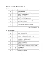
To display detailed error information, use the maintenance-mode function code 82 described in
CHAPTER 5, Subsection 5.3.18 (that is, make the equipment enter the maintenance mode and then
press the
8
and
2
keys). Following the MACHINE ERROR, one of the error codes listed in [ 2 ]
will appear on the LCD.
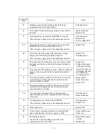
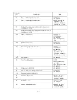
[ 1 ] Error messages on the LCD
Messages on the LCD
Probable Cause
CHECK CARTRIDGE
Open cover, then reinstall ink
cartridge.
(These messages appear alternately.)
Any of the ink cartridges is not loaded.
CHECK DOCUMENT
CHECK ORIGINAL
Remove documents, then
press STOP KEY.
(These messages appear alternately.)
Document jam
(1) The document length exceeds the limitation (400 or 90 cm)
registered by firmware switch WSW16. (Refer to Appendix
2.)
(Both the document front and rear sensors stay ON even
after the document has been fed by the registered length.)
(2) The document rear sensor detects no trailing edge of a
document after the document has been fed by 400 cm.
(The document rear sensor stays ON even after the
document has been fed when the document front and rear
sensors were OFF and ON, respectively.)
Summary of Contents for MFC-5100C
Page 1: ...FACSIMILE EQUIPMENT SERVICE MANUAL MODEL MFC5100C MFC590 ...
Page 4: ...CHAPTER 1 GENERAL DESCRIPTION ...
Page 11: ...CHAPTER 2 INSTALLATION ...
Page 19: ...CHAPTER 3 THEORY OF OPERATION ...
Page 39: ...CHAPTER 4 DISASSEMBLY REASSEMBLY LUBRICATION AND ADJUSTMENT ...
Page 114: ...4 73 7 Paper ejection roller gear and PF roller gear 8 Paper feed roller and PF spring ...
Page 116: ...4 75 11 Purge shaft ...
Page 119: ...4 78 Head Positioning Test Pattern ...
Page 120: ...CHAPTER 5 MAINTENANCE MODE ...
Page 127: ...5 6 Scanning Compensation Data List ...
Page 141: ...5 20 Vertical Alignment Check Pattern ...
Page 148: ...CHAPTER 6 ERROR INDICATION AND TROUBLESHOOTING ...
Page 173: ...MFC5100C MFC590 Appendix 1 EEPROM Customizing Codes ...
Page 176: ...MFC5100C MFC590 Appendix 2 Firmware Switches WSW ...
Page 220: ...A Main PCB 1 6 ...
Page 221: ...A Main PCB 2 6 ...
Page 222: ...A Main PCB 3 6 ...
Page 223: ...A Main PCB 4 6 ...
Page 224: ...A Main PCB 5 6 ...
Page 225: ...A Main PCB 6 6 ...
Page 226: ...R27 100 R28 100 R29 100 R30 100 B Relay PCB ...
Page 227: ...C NCU PCB ...
Page 228: ...D Control Panel PCB 1 2 ...
Page 229: ...D Control Panel PCB 2 2 ...
Page 230: ...E Power Supply PCB ...


