6-4
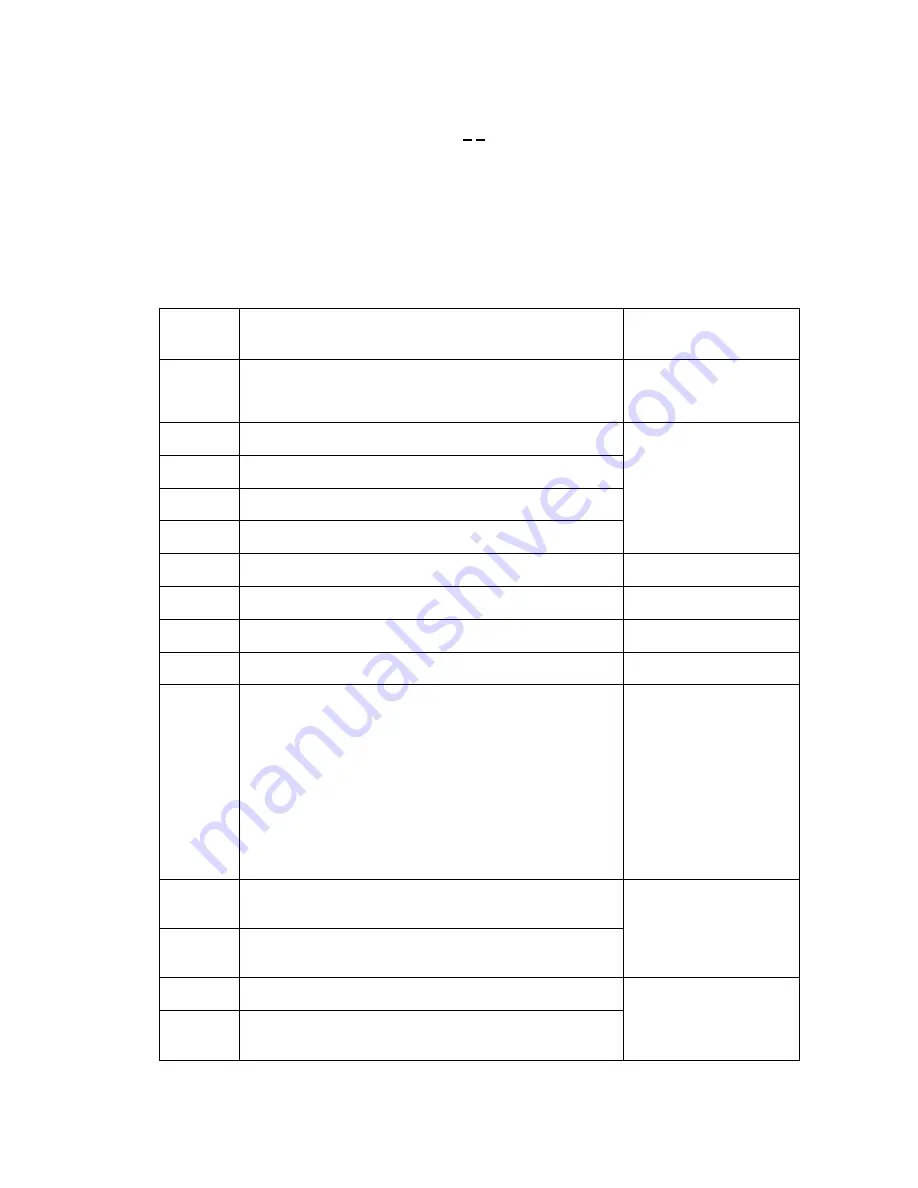
[ 2 ] Error codes shown in the "MACHINE ERROR X X " message
If the LCD shows the "PLS OPEN COVER" message, you can display the detailed error code
following the MACHINE ERROR, by using the maintenance-mode function code 82 described in
CHAPTER 5, Section 5.3.18.
NOTE:
When checking a PCB as instructed in the "Check:" column, check its harness also.
NOTE:
To check sensors, use the maintenance-mode function code 32 described in CHAPTER 5,
Section 5.3.9 (that is, press the
3
and
2
keys in the maintenance mode).
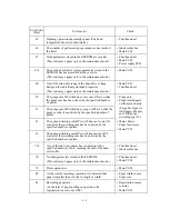
Error Code
(Hex)
Error factor
Check:
25
Ink cartridges had already been loaded when the power
was first applied.
Reload ink cartridges,
referring to the Owner's
Manual.
26
The black ink has run out.
27
The yellow ink has run out.
28
The cyan ink has run out.
29
The magenta ink has run out.
• Ink cartridges
• Cartridge PCB
• Head flat cables
• Main PCB
• Ink empty sensor
2A
No black ink cartridge is loaded.
Load the ink cartridge.
2B
No yellow ink cartridge is loaded.
Load the ink cartridge.
2C
No cyan ink cartridge is loaded.
Load the ink cartridge.
2D
No magenta ink cartridge is loaded.
Load the ink cartridge.
3
∗
Carriage travel error
• Carriage ASSY
• Encoder strip
(Any stains or
scratches? Hooked
correctly?)
• Carriage motor
• Main PCB
• Power supply PCB
• Purge unit
• Main chassis
41
The head drive voltage has not been turned from Low to
High within the specified time.
42
The head drive voltage has not been turned from High to
Low within the specified time.
• Carriage ASSY
• Main PCB
• Print head unit
• Power supply PCB
43
Head thermister broken.
44
Head thermister short-circuited or error in its related
parameters stored in the EEPROM of the main PCB
• Print head unit
• Carriage ASSY
• Main PCB
Summary of Contents for MFC-5100C
Page 1: ...FACSIMILE EQUIPMENT SERVICE MANUAL MODEL MFC5100C MFC590 ...
Page 4: ...CHAPTER 1 GENERAL DESCRIPTION ...
Page 11: ...CHAPTER 2 INSTALLATION ...
Page 19: ...CHAPTER 3 THEORY OF OPERATION ...
Page 39: ...CHAPTER 4 DISASSEMBLY REASSEMBLY LUBRICATION AND ADJUSTMENT ...
Page 114: ...4 73 7 Paper ejection roller gear and PF roller gear 8 Paper feed roller and PF spring ...
Page 116: ...4 75 11 Purge shaft ...
Page 119: ...4 78 Head Positioning Test Pattern ...
Page 120: ...CHAPTER 5 MAINTENANCE MODE ...
Page 127: ...5 6 Scanning Compensation Data List ...
Page 141: ...5 20 Vertical Alignment Check Pattern ...
Page 148: ...CHAPTER 6 ERROR INDICATION AND TROUBLESHOOTING ...
Page 173: ...MFC5100C MFC590 Appendix 1 EEPROM Customizing Codes ...
Page 176: ...MFC5100C MFC590 Appendix 2 Firmware Switches WSW ...
Page 220: ...A Main PCB 1 6 ...
Page 221: ...A Main PCB 2 6 ...
Page 222: ...A Main PCB 3 6 ...
Page 223: ...A Main PCB 4 6 ...
Page 224: ...A Main PCB 5 6 ...
Page 225: ...A Main PCB 6 6 ...
Page 226: ...R27 100 R28 100 R29 100 R30 100 B Relay PCB ...
Page 227: ...C NCU PCB ...
Page 228: ...D Control Panel PCB 1 2 ...
Page 229: ...D Control Panel PCB 2 2 ...
Page 230: ...E Power Supply PCB ...


