6-5
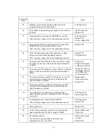
Error Code
(Hex)
Error factor
Check:
45
Flushing operation abnormally ended. (The head
temperature has arisen abnormally.)
• Print head unit
46
The number of performed purge sequences has reached
the limit.
• Ink absorber box
• Main PCB
47
Head parameters stored in the EEPROM are invalid.
(This code may appear only in the maintenance mode.)
• Print head unit
• Main PCB
• Power supply PCB
4D
Error in the head drive voltage parameter stored in the
EEPROM but not accessible at the user site.
(This code may appear only in the maintenance mode.)
• Main PCB
4E
Out of the allowable range of the head drive voltage
designed for individual print head properties.
(This code may appear only in the maintenance mode.)
• Main PCB
• Print head unit
50
The purge cam HP switch does not come ON even after
the purge cam has been driven by the specified number
of pulses.
51
The purge cam HP switch does not go OFF even after the
purge cam has been driven by the specified number of
pulses.
52
The pump switching cam HP switch does not come ON
even after the switching cam has been driven by the
specified number of pulses.
53
The pump switching cam HP switch does not go OFF
even after the switching cam has been driven by the
specified number of pulses.
• Purge unit
• Purge-related gears
on the main chassis
(Purge bevel gear A,
ASF/purge idle gear,
and ASF-purge
switching gear 23)
• Main chassis
• Paper feed motor
• Main PCB
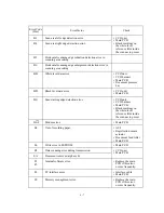
7D
Any of the ink dot counters has counted up to the
specified number of dots, meaning the end of the head
service life.
• Print head unit
• Ink absorber box
7E
No head parameters stored in the EEPROM.
(This code may appear only in the maintenance mode.)
• Print head unit
• Main PCB
7F
Print engine error.
• Main PCB
80
At the start of recording operation, it is detected that
paper is smaller than A4 size in length or width.
• Paper width sensor
• Paper size
83
Recording paper jam.
(At the retry of paper pulling-in operation, the
registration sensor is not OFF.)
• Registration sensor
actuator
• Main PCB
Summary of Contents for MFC-5100C
Page 1: ...FACSIMILE EQUIPMENT SERVICE MANUAL MODEL MFC5100C MFC590 ...
Page 4: ...CHAPTER 1 GENERAL DESCRIPTION ...
Page 11: ...CHAPTER 2 INSTALLATION ...
Page 19: ...CHAPTER 3 THEORY OF OPERATION ...
Page 39: ...CHAPTER 4 DISASSEMBLY REASSEMBLY LUBRICATION AND ADJUSTMENT ...
Page 114: ...4 73 7 Paper ejection roller gear and PF roller gear 8 Paper feed roller and PF spring ...
Page 116: ...4 75 11 Purge shaft ...
Page 119: ...4 78 Head Positioning Test Pattern ...
Page 120: ...CHAPTER 5 MAINTENANCE MODE ...
Page 127: ...5 6 Scanning Compensation Data List ...
Page 141: ...5 20 Vertical Alignment Check Pattern ...
Page 148: ...CHAPTER 6 ERROR INDICATION AND TROUBLESHOOTING ...
Page 173: ...MFC5100C MFC590 Appendix 1 EEPROM Customizing Codes ...
Page 176: ...MFC5100C MFC590 Appendix 2 Firmware Switches WSW ...
Page 220: ...A Main PCB 1 6 ...
Page 221: ...A Main PCB 2 6 ...
Page 222: ...A Main PCB 3 6 ...
Page 223: ...A Main PCB 4 6 ...
Page 224: ...A Main PCB 5 6 ...
Page 225: ...A Main PCB 6 6 ...
Page 226: ...R27 100 R28 100 R29 100 R30 100 B Relay PCB ...
Page 227: ...C NCU PCB ...
Page 228: ...D Control Panel PCB 1 2 ...
Page 229: ...D Control Panel PCB 2 2 ...
Page 230: ...E Power Supply PCB ...


