20
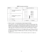
WSW17
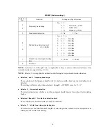
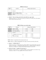
(Function setting 2
)
Selector
No.
Function
Setting and Specifications
1
2
Off-hook alarm
No. 1
2
0
0
:
No alarm
0
1
:
Always valid
1
X
: Valid except when
'call reservation'
is selected.
3
4
Not used.
5
Calendar clock type
0:
U.S.A. type
1: European type
6
Not used.
7
Non-ring reception
0:
OFF
1: ON
8
Not used.
NOTE:
Selector 4 is not applicable to those models having a 2-row LCD.
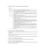
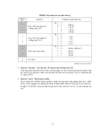
Selectors 1 and 2: Off-hook alarm
These selectors activate or deactivate the alarm function which sounds an alarm when the
communication is completed with the handset being off the hook.
Selector 5:
Calendar clock type
If this selector is set to "0" (USA), the MM/DD/YY hh:mm format applies; if it is set to "1"
(Europe), the DD/MM/YY hh:mm format applies: DD is the day, MM is the month, YY is the last
two digits of the year, hh is the hour, and mm is the minute.
Selector 7:
Non-ring reception
Setting this selector to "1" makes the equipment receive calls without ringer sound if the ring delay
is set to 0.
Summary of Contents for MFC-5100C
Page 1: ...FACSIMILE EQUIPMENT SERVICE MANUAL MODEL MFC5100C MFC590 ...
Page 4: ...CHAPTER 1 GENERAL DESCRIPTION ...
Page 11: ...CHAPTER 2 INSTALLATION ...
Page 19: ...CHAPTER 3 THEORY OF OPERATION ...
Page 39: ...CHAPTER 4 DISASSEMBLY REASSEMBLY LUBRICATION AND ADJUSTMENT ...
Page 114: ...4 73 7 Paper ejection roller gear and PF roller gear 8 Paper feed roller and PF spring ...
Page 116: ...4 75 11 Purge shaft ...
Page 119: ...4 78 Head Positioning Test Pattern ...
Page 120: ...CHAPTER 5 MAINTENANCE MODE ...
Page 127: ...5 6 Scanning Compensation Data List ...
Page 141: ...5 20 Vertical Alignment Check Pattern ...
Page 148: ...CHAPTER 6 ERROR INDICATION AND TROUBLESHOOTING ...
Page 173: ...MFC5100C MFC590 Appendix 1 EEPROM Customizing Codes ...
Page 176: ...MFC5100C MFC590 Appendix 2 Firmware Switches WSW ...
Page 220: ...A Main PCB 1 6 ...
Page 221: ...A Main PCB 2 6 ...
Page 222: ...A Main PCB 3 6 ...
Page 223: ...A Main PCB 4 6 ...
Page 224: ...A Main PCB 5 6 ...
Page 225: ...A Main PCB 6 6 ...
Page 226: ...R27 100 R28 100 R29 100 R30 100 B Relay PCB ...
Page 227: ...C NCU PCB ...
Page 228: ...D Control Panel PCB 1 2 ...
Page 229: ...D Control Panel PCB 2 2 ...
Page 230: ...E Power Supply PCB ...


