22
WSW19
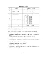
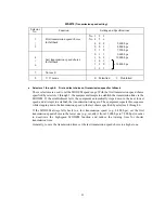
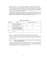
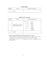
(Transmission speed setting)
Selector
No.
Function
Setting and Specifications
1
|
3
First transmission speed choice
for fallback
No. 1
2
3
No. 4
5
6
0
0
0
:
2,400 bps
0
0
1
:
4,800 bps
0
1
0
:
7,200 bps
4
|
6
Last transmission speed choice
for fallback
0
1
1
:
9,600 bps
1
0
0
:
12,000 bps
1
0
1
:
1
1
0
:
14,400 bps
1
1
1
:
7
Not used.
8
V. 17 mode
0: Permitted
1: Prohibited
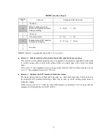
Selectors 1 through 6: First and last choices of transmission speed for fallback
These selectors are used to set the MODEM speed range. With the first transmission speed choice
specified by selectors 1 through 3, the equipment attempts to establish the transmission link via the
MODEM. If the establishment fails, the equipment automatically steps down to the next lowest
speed and attempts to establish the transmission link again. The equipment repeats this sequence
while stepping down the transmission speed to the last choice specified by selectors 4 through 6.
If the MODEM always falls back to a low transmission speed (e.g., 4,800 bps), set the first
transmission speed choice to the lower one (e.g., modify it from 12,000 bps to 7,200 bps) in order
to deactivate the high-speed MODEM function and reduce the training time for shorter
transmission time.
Generally, to save the transmission time, set the last transmission speed choice to a higher one.
Summary of Contents for MFC-5100C
Page 1: ...FACSIMILE EQUIPMENT SERVICE MANUAL MODEL MFC5100C MFC590 ...
Page 4: ...CHAPTER 1 GENERAL DESCRIPTION ...
Page 11: ...CHAPTER 2 INSTALLATION ...
Page 19: ...CHAPTER 3 THEORY OF OPERATION ...
Page 39: ...CHAPTER 4 DISASSEMBLY REASSEMBLY LUBRICATION AND ADJUSTMENT ...
Page 114: ...4 73 7 Paper ejection roller gear and PF roller gear 8 Paper feed roller and PF spring ...
Page 116: ...4 75 11 Purge shaft ...
Page 119: ...4 78 Head Positioning Test Pattern ...
Page 120: ...CHAPTER 5 MAINTENANCE MODE ...
Page 127: ...5 6 Scanning Compensation Data List ...
Page 141: ...5 20 Vertical Alignment Check Pattern ...
Page 148: ...CHAPTER 6 ERROR INDICATION AND TROUBLESHOOTING ...
Page 173: ...MFC5100C MFC590 Appendix 1 EEPROM Customizing Codes ...
Page 176: ...MFC5100C MFC590 Appendix 2 Firmware Switches WSW ...
Page 220: ...A Main PCB 1 6 ...
Page 221: ...A Main PCB 2 6 ...
Page 222: ...A Main PCB 3 6 ...
Page 223: ...A Main PCB 4 6 ...
Page 224: ...A Main PCB 5 6 ...
Page 225: ...A Main PCB 6 6 ...
Page 226: ...R27 100 R28 100 R29 100 R30 100 B Relay PCB ...
Page 227: ...C NCU PCB ...
Page 228: ...D Control Panel PCB 1 2 ...
Page 229: ...D Control Panel PCB 2 2 ...
Page 230: ...E Power Supply PCB ...


