31
WSW31
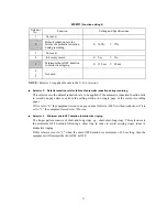
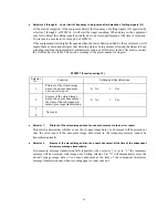
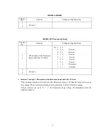
(Function setting 9)
Selector
No.
Function
Setting and Specifications
1
Not used.
2
Default reduction rate for
failure of automatic reduction
during recording
0: 100%
1: 70%
3
Not used.
4
Ink empty sensor
0: Yes
1: No
5
Minimum short-OFF duration
in distinctive ringing
0: 130 ms
1: 90 ms
6
|
8
Not used.
NOTE:
Selector 5 is applicable only to the U.S.A. versions.
Selector 2:
Default reduction rate for failure of automatic reduction during recording
This selector sets the default reduction rate to be applied if the automatic reduction function fails
to record one-page data sent from the calling station in a single page of the current recording
paper.
If it is set to "0," the equipment records one-page data at full size (100%) without reduction; if it is
set to "1," the equipment records it at 70% size.
Selector 5
Minimum short-OFF duration in distinctive ringing
The ringer pattern consists of short and long rings, e.g., short-short-long rings. This selector sets
the minimum OFF duration following a short ring in order to avoid missing ringer tones in
distinctive ringing.
If this selector is set to "1," when the short-OFF duration is a minimum of 90 ms long, then the
equipment will interpret the short-OFF as OFF.
Summary of Contents for MFC-5100C
Page 1: ...FACSIMILE EQUIPMENT SERVICE MANUAL MODEL MFC5100C MFC590 ...
Page 4: ...CHAPTER 1 GENERAL DESCRIPTION ...
Page 11: ...CHAPTER 2 INSTALLATION ...
Page 19: ...CHAPTER 3 THEORY OF OPERATION ...
Page 39: ...CHAPTER 4 DISASSEMBLY REASSEMBLY LUBRICATION AND ADJUSTMENT ...
Page 114: ...4 73 7 Paper ejection roller gear and PF roller gear 8 Paper feed roller and PF spring ...
Page 116: ...4 75 11 Purge shaft ...
Page 119: ...4 78 Head Positioning Test Pattern ...
Page 120: ...CHAPTER 5 MAINTENANCE MODE ...
Page 127: ...5 6 Scanning Compensation Data List ...
Page 141: ...5 20 Vertical Alignment Check Pattern ...
Page 148: ...CHAPTER 6 ERROR INDICATION AND TROUBLESHOOTING ...
Page 173: ...MFC5100C MFC590 Appendix 1 EEPROM Customizing Codes ...
Page 176: ...MFC5100C MFC590 Appendix 2 Firmware Switches WSW ...
Page 220: ...A Main PCB 1 6 ...
Page 221: ...A Main PCB 2 6 ...
Page 222: ...A Main PCB 3 6 ...
Page 223: ...A Main PCB 4 6 ...
Page 224: ...A Main PCB 5 6 ...
Page 225: ...A Main PCB 6 6 ...
Page 226: ...R27 100 R28 100 R29 100 R30 100 B Relay PCB ...
Page 227: ...C NCU PCB ...
Page 228: ...D Control Panel PCB 1 2 ...
Page 229: ...D Control Panel PCB 2 2 ...
Page 230: ...E Power Supply PCB ...

