3 -1 3
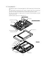
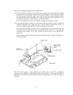
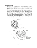
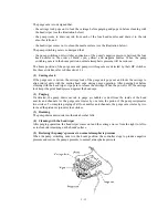
The purge cam is so designed that:
- the carriage lock pops out to lock the carriage before purging and pops in before cleaning with
the head wiper (see the illustration below),
- the pump works to draw out ink from each of the four head nozzles and drain it to the ink
absorber felts, and
- the head wiper comes out to clean the nozzle surface (see the illustration below).
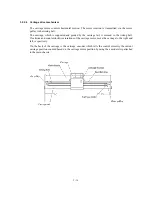
The pump switching cam is so designed that:
- the pump switching unit switches application of the pump’s negative pressure between the four
head nozzles in the order of black, cyan, yellow, and magenta nozzles. When the pump
switching cam is in the home position, normal atmospheric pressure will be restored.
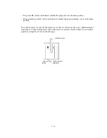
The home position of the purge cam and pump switching cam are detected by their HP switches.
For those switches, refer to Subsection 3.2.3.
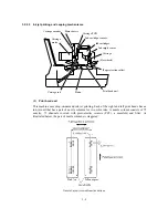
(1) Carriage lock
If the purge cam is driven, the carriage lock of the purge unit pops out and locks the carriage to
align ink-jet units with the mating head caps during purge operation. After purging but before
cleaning with the head wiper, it pops in to release the carriage. When the power is off, the carriage
lock keeps the print heads pressed against the head caps.
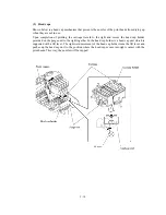
(2) Purging
If activated, the pump draws out ink to purge air bubbles or dust from the inside of the head
nozzles and channels. As the purge cam rotates by one turn, the piston of the pump reciprocates
two strokes. To complete purging of all four nozzles and channels, the purge cam rotates by two
turns ad the piston reciprocates four strokes.
(3) Draining
The pump drains drawn ink into the ink absorber felts.
(4) Cleaning with the head wiper
After purging operation, the head wiper comes out and the carriage moves from the right to left so
as to clean ink remaining on the heads’ surface.
(5) Restoring the pump’s pressure to normal atmospheric pressure
When the pump switching cam is in the home position, the controller stops to produce negative
pressure and restore the pump’s pressure to normal atmospheric pressure.
Summary of Contents for MFC-5100C
Page 1: ...FACSIMILE EQUIPMENT SERVICE MANUAL MODEL MFC5100C MFC590 ...
Page 4: ...CHAPTER 1 GENERAL DESCRIPTION ...
Page 11: ...CHAPTER 2 INSTALLATION ...
Page 19: ...CHAPTER 3 THEORY OF OPERATION ...
Page 39: ...CHAPTER 4 DISASSEMBLY REASSEMBLY LUBRICATION AND ADJUSTMENT ...
Page 114: ...4 73 7 Paper ejection roller gear and PF roller gear 8 Paper feed roller and PF spring ...
Page 116: ...4 75 11 Purge shaft ...
Page 119: ...4 78 Head Positioning Test Pattern ...
Page 120: ...CHAPTER 5 MAINTENANCE MODE ...
Page 127: ...5 6 Scanning Compensation Data List ...
Page 141: ...5 20 Vertical Alignment Check Pattern ...
Page 148: ...CHAPTER 6 ERROR INDICATION AND TROUBLESHOOTING ...
Page 173: ...MFC5100C MFC590 Appendix 1 EEPROM Customizing Codes ...
Page 176: ...MFC5100C MFC590 Appendix 2 Firmware Switches WSW ...
Page 220: ...A Main PCB 1 6 ...
Page 221: ...A Main PCB 2 6 ...
Page 222: ...A Main PCB 3 6 ...
Page 223: ...A Main PCB 4 6 ...
Page 224: ...A Main PCB 5 6 ...
Page 225: ...A Main PCB 6 6 ...
Page 226: ...R27 100 R28 100 R29 100 R30 100 B Relay PCB ...
Page 227: ...C NCU PCB ...
Page 228: ...D Control Panel PCB 1 2 ...
Page 229: ...D Control Panel PCB 2 2 ...
Page 230: ...E Power Supply PCB ...


