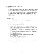
7-12
7.5.6 Firmware Switch Setting and Printout
[ A ] Firmware switch setting
Function
The facsimile equipment incorporates the following firmware switch functions which may be
activated with the procedures using the control panel keys and buttons.
The firmware switches have been set at the factory in conformity to the communications standards
and codes of each country. Do not disturb them unless necessary. Some firmware switches may not
be applicable in some versions. The firmware switch data list indicates "Not used." for those
inapplicable switches.
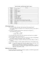
Firmware Switches (WSW01 through WSW50)
WSW No.
Function
WSW01
Dial pulse setting
WSW02
Tone signal setting
WSW03
PABX mode setting
WSW04
TRANSFER facility setting
WSW05
1st dial tone and busy tone detection
WSW06
Pause
key setting and 2nd dial tone detection
WSW07
Dial tone setting 1
WSW08
Dial tone setting 2
WSW09
Protocol definition 1
WSW10
Protocol definition 2
WSW11
Busy tone setting
WSW12
Signal detection condition setting
WSW13
Modem setting
WSW14
AUTO ANS facility setting
WSW15
REDIAL facility setting
WSW16
Function setting 1
WSW17
Function setting 2
WSW18
Function setting 3
WSW19
Transmission speed setting
WSW20
Overseas communications mode setting
WSW21
TAD setting 1
WSW22
ECM and copy resolution setting
WSW23
Communications setting
WSW24
TAD setting 2
WSW25
TAD setting 3
WSW26
Function setting 4
WSW27
Function setting 5
WSW28
Function setting 6
WSW29
Function setting 7
WSW30
Not used.
WSW31
Function setting 9
WSW32
Function setting 10
WSW33
Function setting 11
Summary of Contents for MFC-5200C
Page 1: ...FACSIMILE EQUIPMENT SERVICE MANUAL MODEL MFC5200C MFC890 ...
Page 7: ...CHAPTER 1 PARTS NAMES FUNCTIONS ...
Page 8: ...CHAPTER 1 PARTS NAMES FUNCTIONS CONTENTS 1 1 EQUIPMENT OUTLINE 1 1 1 2 CONTROL PANEL 1 3 ...
Page 13: ...CHAPTER 2 SPECIFICATIONS ...
Page 18: ...2 4 2 1 4 Environmental Condition ...
Page 23: ...CHAPTER 3 INSTALLATION ...
Page 26: ...3 2 3 2 UNPACKING THE MACHINE The equipment consists of the following major components ...
Page 34: ...CHAPTER 4 THEORY OF OPERATION ...
Page 54: ...CHAPTER 5 MAINTENANCE ...
Page 60: ...CHAPTER 6 DISASSEMBLY REASSEMBLY LUBRICATION AND ADJUSTMENT ...
Page 141: ...6 79 2 Separation roller and document feed roller 3 Document ejection roller ...
Page 146: ...6 84 11 Purge shaft EM4 Main chassis ...
Page 151: ...CHAPTER 7 MAINTENANCE MODE ...
Page 160: ...7 8 Scanning Compensation Data List ...
Page 174: ...7 22 Vertical Alignment Check Pattern ...
Page 183: ...CHAPTER 8 ERROR INDICATION AND TROUBLESHOOTING ...
Page 213: ...8 29 4 Close the manual feed cover ...
Page 214: ...MFC5200C MFC890 Appendix 1 Serial No Descriptions ...
Page 216: ... 2 PRINTER HEAD UNIT Location ...
Page 228: ...MFC5200C MFC890 Appendix 3 EEPROM Customizing Codes ...
Page 231: ...MFC5200C MFC890 Appendix 4 Firmware Switches WSW ...
Page 274: ...MFC5200C MFC890 Appendix 5 Re Packing Instructions ...
Page 276: ... 8 Place the machine in the original box with the original packaging material ...
Page 277: ...MFC5200C MFC890 Appendix 6 Wiring Diagram ...
Page 280: ...A Main PCB 1 4 MFC5200C ...
Page 281: ...A Main PCB 2 4 MFC5200C ...
Page 282: ...A Main PCB 3 4 MFC5200C ...
Page 283: ...A Main PCB 4 4 MFC5200C ...
Page 284: ...B Driver PCB 1 2 ...
Page 285: ...B Driver PCB 2 2 ...
Page 286: ...C NCU PCB MFC5200C ...
Page 287: ...D Control Panel PCB 1 2 MFC5200C ...
Page 288: ...D Control Panel PCB 1 2 MFC890 ...
Page 289: ...D Control Panel PCB 2 2 ...
Page 290: ...E Power Supply PCB MFC5200C ...
Page 291: ...F Carriage PCB ...
Page 292: ...G Media PCB 1 2 ...
Page 293: ...G Media PCB 2 2 ...


