8-3
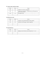
Messages on the LCD
Probable Cause
LOW TEMPERATURE
Room temperature is below
spec.
The temperature inside the machine is too low.
MANUAL TRAY OPEN
Please close the Manual Tray.
The manual feed slot cover is not closed. If it is closed, check
the sensor by using maintenance-mode function 32. (Refer to
CHAPTER 7, Subsection 7.5.9.)
The manual feed slot cover sensor or the main PCB is defective.
NEAR EMPTY CYAN
NEAR EMPTY MGENT
NEAR EMPTY YELLW
NEAR EMPTY BLACK
The ink empty sensor detects that the ink cartridge (cyan,
magenta, yellow, or black) is near empty.
Even if any of these messages is displayed, color printing is still
possible.
PAPER JAM
Open cover, then remove
jammed paper.
(These messages appear alternately.)
The registration sensor detects that a paper jam has occurred.
PC BUSY OR FAIL
Check PC cable, then press
STOP KEY.
(These messages appear alternately.)
After connected with the host computer, the equipment has
received no response from the computer. (A communications
error has occurred.)
PLS OPEN COVER
To display the relating detailed error code, use maintenance-
mode function code 82. (Refer to CHAPTER 7, Subsection
7.5.18.)
If this message appears, open and close the scanner unit. The
message may disappear if opening/closing the scanner unit
removes the error. If the error persists, the "MACHINE ERROR
X X" will appear instead of this message.
SCAN LAMP WARMUP
After the fluorescent lamp in the CCD unit had been OFF, the
scanning operation got started. Until the fluorescent lamp
becomes stabilized in lighting, the scanning operation will be
delayed.
SCANNER ERROR
In the scanning compensation data list printed by the
maintenance-mode function code 05 (refer to CHAPTER 7,
Subsection 7.5.2), fifty percent or more of the white level data
is faulty.
(This message may appear only in the maintenance mode)
If only an alarm beep is heard without any message on the LCD when the equipment is turned on,
then the ROM or RAM will be defective.
Summary of Contents for MFC-5200C
Page 1: ...FACSIMILE EQUIPMENT SERVICE MANUAL MODEL MFC5200C MFC890 ...
Page 7: ...CHAPTER 1 PARTS NAMES FUNCTIONS ...
Page 8: ...CHAPTER 1 PARTS NAMES FUNCTIONS CONTENTS 1 1 EQUIPMENT OUTLINE 1 1 1 2 CONTROL PANEL 1 3 ...
Page 13: ...CHAPTER 2 SPECIFICATIONS ...
Page 18: ...2 4 2 1 4 Environmental Condition ...
Page 23: ...CHAPTER 3 INSTALLATION ...
Page 26: ...3 2 3 2 UNPACKING THE MACHINE The equipment consists of the following major components ...
Page 34: ...CHAPTER 4 THEORY OF OPERATION ...
Page 54: ...CHAPTER 5 MAINTENANCE ...
Page 60: ...CHAPTER 6 DISASSEMBLY REASSEMBLY LUBRICATION AND ADJUSTMENT ...
Page 141: ...6 79 2 Separation roller and document feed roller 3 Document ejection roller ...
Page 146: ...6 84 11 Purge shaft EM4 Main chassis ...
Page 151: ...CHAPTER 7 MAINTENANCE MODE ...
Page 160: ...7 8 Scanning Compensation Data List ...
Page 174: ...7 22 Vertical Alignment Check Pattern ...
Page 183: ...CHAPTER 8 ERROR INDICATION AND TROUBLESHOOTING ...
Page 213: ...8 29 4 Close the manual feed cover ...
Page 214: ...MFC5200C MFC890 Appendix 1 Serial No Descriptions ...
Page 216: ... 2 PRINTER HEAD UNIT Location ...
Page 228: ...MFC5200C MFC890 Appendix 3 EEPROM Customizing Codes ...
Page 231: ...MFC5200C MFC890 Appendix 4 Firmware Switches WSW ...
Page 274: ...MFC5200C MFC890 Appendix 5 Re Packing Instructions ...
Page 276: ... 8 Place the machine in the original box with the original packaging material ...
Page 277: ...MFC5200C MFC890 Appendix 6 Wiring Diagram ...
Page 280: ...A Main PCB 1 4 MFC5200C ...
Page 281: ...A Main PCB 2 4 MFC5200C ...
Page 282: ...A Main PCB 3 4 MFC5200C ...
Page 283: ...A Main PCB 4 4 MFC5200C ...
Page 284: ...B Driver PCB 1 2 ...
Page 285: ...B Driver PCB 2 2 ...
Page 286: ...C NCU PCB MFC5200C ...
Page 287: ...D Control Panel PCB 1 2 MFC5200C ...
Page 288: ...D Control Panel PCB 1 2 MFC890 ...
Page 289: ...D Control Panel PCB 2 2 ...
Page 290: ...E Power Supply PCB MFC5200C ...
Page 291: ...F Carriage PCB ...
Page 292: ...G Media PCB 1 2 ...
Page 293: ...G Media PCB 2 2 ...


