background image

IV

 - 5

1.1

Ink Cartridges

During disassembly jobs, both of the ink cartridges should be removed.  The following
procedure should apply only when you need to make operation checks.

If you have initialized the EEPROM, plugging the power cord into an electrical socket will
show the "SET CARTRIDGES" and "PLS OPEN COVER" alternately on the LCD.  Then
follow the steps given below.

If ink empty LED blinks or comes ON during printing, press the Ink Management key,
choose "3.REPLACE INK" by using the right or left arrow key, and press the Set key.  The
"PLS OPEN COVER" appears on the LCD.  Then follow the steps given below.

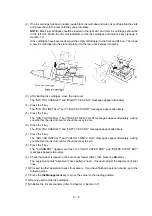
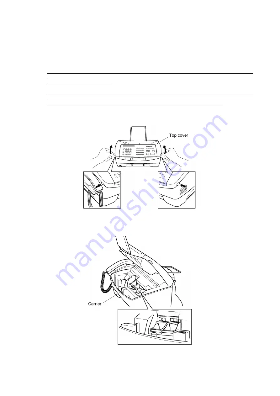
(1) Open the top cover.

A few seconds later, the carrier will move to the loading position.

Summary of Contents for MFC-7050C

Page 1: ...FACSIMILE EQUIPMENT SERVICE MANUAL MODEL MFC7050C ...

Page 2: ...ht Brother 1999 All rights reserved No part of this publication may be reproduced in any form or by any means without permission in writing from the publisher Specifications are subject to change without notice ...

Page 3: ...ate maintenance so that the facsimile equipment is always in best condition for the customer the service personnel must adequately understand and apply this manual This manual is made up of six chapters and appendices CHAPTER I GENERAL DESCRIPTION CHAPTER II INSTALLATION CHAPTER III THEORY OF OPERATION CHAPTER IV DISASSEMBLY REASSEMBLY AND LUBRICATION CHAPTER V MAINTENANCE MODE CHAPTER VI ERROR IN...

Page 4: ...CHAPTER I GENERAL DESCRIPTION ...

Page 5: ...CONTENTS 1 EQUIPMENT OUTLINE I 1 1 1 External Appearance and Weight I 1 1 2 Components I 1 2 SPECIFICATIONS I 2 ...

Page 6: ...ernal Appearance and Weight The figure below shows the equipment appearance and approximate dimensions Weight Machine proper Approx 7 kg In package Approx 11 kg 1 2 Components The equipment consists of the following major components ...

Page 7: ...actory Std 1 100 sheets Optional ASF N A ASF Capacity No of sheets 100 Number of Ink Cartridges 2 Starter Ink Cartridge Life 5 duty Approx 600 pages black Approx 200 pages color Approx 300 pages photo optional Interface IEEE1284 Bidirectional Network Card N A SCANNER Color Mono Mono CIS Resolution dpi 100 x 100 200 x 200 400 x 400 600 x 600 Optical 200 Gray Scale 256 shades Twain Yes Scanning Spee...

Page 8: ...ng N A TAD Interface Yes Next FAX Reservation N A Coverpage Yes Super Polling Type Std Seq Password Check N A Memory Reception Yes 85 pages Delayed Timer Yes 1 timer Broadcasting Yes Up to 174 locations Call Reservation N A Call Back Message N A ITU SUB Addressing N A BFT Compatible N A Color Fax Mode N A Fax Edit Mode N A Color File Transfer Yes via BFT from PC Multi Transmission N A DUAL ACCESS ...

Page 9: ...tional Feature Energy Star Compliance N A Memory Standard 2 MB Memory Opt Upgrade N A Simultaneous Operation Yes FAX PRINTER SCAN PRINTER COPY PRINTER PC FAX Host Software Std Yes Host Interface Scan Print PC fax Bi Centro Video Capture Video Print Yes NTSC PC Fax Protocol Compliance CLASS 1 Data Modem N A Bundled Software PC FAX Send Receive Yes SMSI Internet Fax Yes Netcentric in Visioneer Color...

Page 10: ...CHAPTER II INSTALLATION ...

Page 11: ...CONTENTS 1 INSTALLING THE UPDATE DATA TO THE FACSIMILE EQUIPMENT II 1 ...

Page 12: ...Windows 95 OS Windows 3 1 3 11 or Windows 95 98 Connecting the facsimile equipment to your computer 1 Make sure that the equipment s power cord is unplugged from a wall socket 2 Make sure that your computer is powered off 3 Connect the interface cable to the parallel interface port on the back of the equipment and secure it with the lock wires 4 Connect the other end of the interface cable to the ...

Page 13: ...and line and press the ENTER key 4 Check that your computer is connected with the facsimile equipment correctly 5 To start the transfer utility transmitting the update data to the flash ROM of the facsimile equipment type the following PPP EXE filename Then press the ENTER key As the installation proceeds the equipment shows the following messages on the LCD in order Receiving Image Erasing Flash ...

Page 14: ...CHAPTER III THEORY OF OPERATION ...

Page 15: ... III 5 2 2 1 Paper pulling in registration feeding and ejecting mechanisms III 5 2 2 2 Ink jet printing and capping mechanisms III 8 2 2 3 Carrier drive mechanism III 10 2 3 Sensors and Actuators III 11 3 CONTROL ELECTRONICS III 13 3 1 Configuration III 13 3 2 Main PCB III 14 3 3 NCU PCB III 16 3 4 Control Panel PCB III 17 3 5 Power Supply PCB III 18 3 6 Interface PCB III 19 ...

Page 16: ...III 1 1 OVERVIEW ...

Page 17: ...sms n SCANNER MECHANISM Document feeding and ejecting mechanism Document scanning mechanism n INK JET PRINTING MECHANISM Paper pulling in registration feeding and ejecting mechanisms Ink jet printing and head capping mechanisms Carrier drive mechanism n SENSORS AND ACTUATORS ...

Page 18: ...f the operator sets documents on the top cover and starts the scanning operation the scanner motor rotates so that the ADF which consists of the separation roller ASSY and ADF parts feeds those documents into the equipment starting from the bottom sheet to the top page by page Each document advances with the document feed roller ASSY to the scanner and then it is fed out of the equipment with the ...

Page 19: ...sengage the planet gear 23 ASSY from the gear 19 47 This allows you to pull back a document if jammed in the backward direction Viewed from the right 2 1 2 Scanner The scanner uses a contact image sensor CIS unit which consists of an LED array illuminating documents a self focus lens array collecting the reflected light a CIS PCB carrying out photoelectric conversion to output picture element data...

Page 20: ...5 2 2 Ink Jet Printing Mechanism 2 2 1 Paper pulling in registration feeding and ejecting mechanisms The paper pulling in registration feeding and ejecting mechanisms are driven by a single paper feed motor ...

Page 21: ...counterclockwise to pull in paper from the ASF a sheet at a time Since the gear is a sector gear it will stop when the toothless section comes to the joint with the mating middle gear B idle gear The motor continues to rotate clockwise for driving the registration mechanism The rotational torque is transmitted via the gear train to the feed gear that rotates counterclockwise This registers the lea...

Page 22: ... rotates clockwise to feed paper The torque is further transmitted via the middle gears to the exit gear After the paper passes through the print head it will be ejected onto the paper tray The rotational torque is transmitted also to the friction gear 2 which is engaged with the teeth of the supply gear so the supply gear rotates and comes back to the initial position ...

Page 23: ... black cartridge with an optional photo cartridge containing black light cyan and light magenta ink the dual heads provide color and photo quality printing The ink jet head of the black cartridge has a total of 208 nozzles That of the color cartridge and photo cartridge has a total of 192 nozzles for three colors of ink 64 nozzles color As the carrier holding the ink cartridges travels at the prin...

Page 24: ...ith the print heads Capping the nozzles of the print heads this way prevents them from drying up or becoming dirtied with dust when they are not in use If the carrier travels to the left for printing the head cap unit goes down to the previous position with the springs The above head capping mechanism moves also the head wiper unit up When the carrier travels to the left the wipers clean ink remai...

Page 25: ...e carrier which is supported and guided by the main shaft is secured to the timing belt Clockwise and counterclockwise rotations of the carrier transport motor move the carrier to the right and left respectively On the back of the carrier is the carrier home position sensor photointerrupter which tells the control circuitry whether the carrier is in the home position ...

Page 26: ...op cover is closed Registration sensor which detects the leading and trailing edges of paper which allows the controller to determine the registration timing and check paper jam Document front sensor which detects the presence of documents Document rear sensor which detects the leading and trailing edges of pages to tell the control circuitry when the leading edge of a new page has reached the sta...

Page 27: ...III 12 Location of Sensors and Actuators ...

Page 28: ...nt 1 On the main PCB is the registration sensor 2 On the cover sensor PCB is the cover sensor 3 On the hook switch PCB is the hook switch sensor 4 On the document sensor PCB are these sensors Document front sensor PH1 Document rear sensor PH2 5 On the sensor FPC is the carrier home position sensor 6 On the ink empty sensor PCB is the ink empty sensor ...

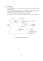
Page 29: ...hich is the nucleus controlling the entire operation of the equipment consists of an ASIC gate array memories MODEM motor drive circuitry sensor detection circuitry and analog circuits for scanning and printing Block Diagram of Main PCB ...

Page 30: ...III 15 ...

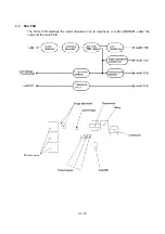
Page 31: ...III 16 3 3 NCU PCB The NCU PCB switches the communications line to telephone or built in MODEM under the control of the main PCB ...

Page 32: ... unit consists of a gate array an LCD and LEDs which are controlled by the gate array according to commands issued from the control CPU on the main PCB The calendar clock is backed up by the backup circuit on the main PCB The panel FPC is a flexible keyboard PCB which integrates the key matrix having rubber keytops Control Panel PCB and its Related Circuit ...

Page 33: ...rface PCB to the main PCB The 30V source is stabilized and fed to the scanner motor for advancing documents paper feed motor for feeding documents and recording paper carrier transport motor for moving the carrier thermal ink jet print heads and LED array of the CIS unit The 5V source is stabilized and fed to the ASIC Centronics interface circuit memories and video IC Power Supply Circuit ...

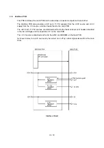
Page 34: ...ly from the 5V source and then feeds them to the main PCB The 22V and 11 75V sources are stabilized and fed to the thermal ink jet print heads embedded in the ink cartridges and the head driver IC on the main PCB The 3 3V source is stabilized and fed to the ASIC and MODEM on the main PCB As shown below the 22V source may be turned on or off by control signals issued from the main PCB Interface Cir...

Page 35: ...CHAPTER IV DISASSEMBLY REASSEMBLY AND LUBRICATION ...

Page 36: ...8 Auto Sheet Feeder ASF IV 21 1 9 Inner Cover IV 22 1 10 Battery ASSY IV 23 1 11 Upper Cover ASSY IV 24 1 12 Top Cover ASSY IV 26 1 13 Handset Mount and Hook Switch PCB ASSY IV 29 1 14 Top Cover Lock Spring IV 31 1 15 Speaker and Cover Sensor PCB IV 31 1 16 Main PCB and Insulation Film IV 32 1 17 Video PCB IV 35 1 18 Ink Empty Sensor PCB ASSY IV 36 1 19 Bottom Plate IV 38 1 20 Power Supply PCB and...

Page 37: ...SSY IV 55 1 33 Ink Foam IV 56 1 34 Harness Routing IV 57 2 LUBRICATION IV 58 1 Document feed roller ASSY and document ejection roller ASSY IV 58 2 Control panel locks IV 59 3 Scanner frame ASSY and separation roller gear IV 59 4 Top cover lock spring IV 60 5 Gear plate ASSY IV 60 6 Hinges IV 61 7 Frame chassis ASSY IV 61 8 Idle pulley holder IV 62 9 Maintenance ASSY IV 62 10 Exit roller ASSY IV 63...

Page 38: ...luminum foil 6 Be sure to reinsert self tapping screws correctly if removed 7 Tighten screws to the torque values listed on the following pages 8 When connecting or disconnecting cable connectors hold the connector bodies not the cables If the connector has a lock always slide the connector lock to unlock it 9 Before reassembly apply the specified lubricant to the specified points Refer to Section...

Page 39: ... M3x6 1 78 20 8 2 Min 20 Min 2 Top cover Taptite bind B M4x12 2 98 20 10 2 Min 29 Min 3 Hinges Taptite bind B M4x12 4 98 20 10 2 Min 29 Min 3 Handset mount Taptite cup B M3x10 2 78 20 8 2 Min 20 Min 2 Top cover lock spring Taptite bind B M4x12 1 98 20 10 2 Min 29 Min 3 Speaker spring Taptite bind B M4x12 1 98 20 10 2 Min 29 Min 3 Main PCB Taptite cup S M3x6 4 78 20 8 2 Min 20 Min 2 Video PCB Tapti...

Page 40: ...nsion the document tray the paper tray and the ink cartridges if loaded Not shown below n n How to Access the Object Component On the next page is a disassembly order flow which helps you access the object components To remove the paper feed motor for example first find it on the flow and learn its number in this case You need to remove parts numbered and so as to access the paper feed motor Unles...

Page 41: ...IV 4 n n Disassembly Order Flow ...

Page 42: ...electrical socket will show the SET CARTRIDGES and PLS OPEN COVER alternately on the LCD Then follow the steps given below If ink empty LED blinks or comes ON during printing press the Ink Management key choose 3 REPLACE INK by using the right or left arrow key and press the Set key The PLS OPEN COVER appears on the LCD Then follow the steps given below 1 Open the top cover A few seconds later the...

Page 43: ...the 1 key The DID YOU INSTALL and BLACK 1 NEW 2 OLD messages appear alternately asking you whether the ink dot counter should be reset to zero 6 Press the 1 key The DID YOU CHANGE and LEFT 1 YES 2 NO messages appear alternately 7 Press the 1 key The DID YOU INSTALL and COLOR 1 NEW 2 OLD messages appear alternately asking you whether the ink dot counter should be reset to zero 8 Press the 1 key The...

Page 44: ... 1 Remove the interlock keys from the carrier n n Reassembling Notes Set the violet interlock key at the left and the gray one at the right As shown above fit the boss of each interlock key in the hole provided on the carrier ...

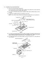
Page 45: ...unhook those arms from bosses x provided on the scanner frame ASSY Then slide the control panel ASSY to the front arrow ƒ to release its bosses y from the grooves of the scanner frame ASSY 3 Slightly lift up the control panel ASSY and disconnect the panel main harness from the control panel PCB n n Reassembling Notes Make sure that the panel main harness is not slack or pinched between the scanner...

Page 46: ... screw 3 To replace the antistatic brushes and shield film remove them NOTE Once removed they will become unusable and new parts will have to be put back in 4 To remove the document pressure bar pull either of supports a provided on the panel rear cover outwards and then lift the pressure bar up and towards the rear to release the three tabs from the cutouts provided in the panel rear cover The sp...

Page 47: ...ear cover 8 Fully turn the document front sensor actuator to the rear and lift it up 9 Unhook the document sensor PCB from two Y latches 10 Unhook the control panel PCB from four Z latches 11 Slightly lift up the control panel PCB then unlock the LCD cable connector and disconnect the LCD flat cable Next unlock the FPC key connector and disconnect the FPC key ...

Page 48: ...fective and requires replacement n n Reassembling Notes Before reinstalling the LCD to the control panel wipe fingerprints or dust off the LCD surface and control panel window with a soft cloth A new LCD is covered with a protection sheet Before installing it remove the protection sheet To put the LCD back into place insert the tip of a flat screwdriver under clamp A from the rear push up clamp A ...

Page 49: ...rm rib b and shift the document ejection roller ASSY to the right and upwards without removing the shield film NOTE Take care not to break the arm ribs They may easily break n n Reassembling Notes Make sure that the shield film is on the document ejection roller gear and not bent down by that gear Once removed the shield film will become unusable and new one will have to be put back in ...

Page 50: ...IS film Shield film CIS unit shown on the next page Lightly pull up the arm move the CIS unit to the left and lift up the right edge of the CIS unit While holding up the CIS unit disconnect the CIS harness CIS leaf springs shown on the next page NOTE Once removed the CIS film and shield film will become unusable and new ones will have to be put back in ...

Page 51: ...IV 14 2 Remove the two screws from the scanner frame ASSY See the illustration on the next page ...

Page 52: ...er frame ASSY to release the three pawls provided on the front end from the top cover then hold up the ASSY and disconnect the scanner motor harness and CIS harness if the CIS is mounted 4 Take off the grounding terminals by removing the screws ...

Page 53: ... the screw from the scanner motor and turn the motor clockwise to release from the latch 7 Remove the pinch roller leaf spring by removing the screw then lift up the pinch rollers and shaft 8 Remove the control panel locks leaf springs by removing the screws ...

Page 54: ...rows and in this order as shown below Then remove the pressure rollers and shaft 10 Slightly push down the arm in the direction of arrow and shift the separation roller gear to the right arrow when viewed from the rear Then shift the separation roller to the right arrow ƒ and take it up ...

Page 55: ... off the scanner drive unit by removing the two screws The separation roller gear also comes off 12 Push down the CIS side spring to release it from the latch then pull it out to the right when viewed from the rear ...

Page 56: ...rness to the CIS unit if mounted route the panel main harness through the cutout provided in the scanner frame ASSY When reinstalling the CIS unit first connect the CIS harness insert the left end under the arm of the scanner frame put the CIS unit into the scanner frame and move it to right see the illustration given on page IV 14 When attaching the CIS film align the right left and rear edges of...

Page 57: ...IV 20 1 7 Rear Cover 1 Remove the four screws from the rear cover 2 Slightly pull the top of the rear cover to the rear and lift up the rear cover ...

Page 58: ...press the latch inwards to unhook it from the square hole provided in the frame chassis then lift up the ASF n n Reassembling Notes When reinstalling the ASF fit the boss provided on the right end into the cutout of the paper feed motor bracket If you replace the ASF with a new one attach a new harness protection film to the new ASF as illustrated below Route the paper feed motor harness on the ha...

Page 59: ...ws from the inner cover 2 Remove the inner cover To release the bottom end of the inner cover from the guide provided on the upper cover lightly pull the top of the inner cover to the rear until it comes out of the upper cover and then pull it up ...

Page 60: ... steps below 1 Plug the power cord of the facsimile equipment into a power outlet 2 Disconnect the battery harness from the main PCB and take out the battery ASSY from the pocket provided on the upper cover 3 Connect the removed battery ASSY to the main PCB again and put the battery ASSY on the main PCB 4 Unplug the power cord 5 Handle jobs involving the removal of the upper cover ASSY 6 After com...

Page 61: ...if the battery ASSY has not been removed from the main PCB Cover sensor harness Panel main harness CIS harness Speaker harness Hook switch harness Scanner motor harness Battery harness if not disconnected yet 2 Remove screw b that secures the three grounding wires 3 Remove two screws a ...

Page 62: ...IV 25 4 Open the top cover 5 Remove two screws c 6 Lift the upper cover ASSY up and off the lower cover n n Reassembling Notes Route the harnesses as shown in Section 1 34 ...

Page 63: ... cover in the direction of the arrow 4 Place the top cover upside down 5 Remove two screws from each of the hinges R and L then take off those hinges See the illustration given on the next page The grounding wires panel main harness and CIS harness also come off 6 Cut off the binder that secures the scanner motor harness to the support provided on the top cover ...

Page 64: ...ounding wires as illustrated above taking care not to pinch them between the hinge and top cover As illustrated above route the scanner motor harness and secure it to the support with a binder so that the distance from the ferrite core to the secured point comes to 50 5 mm ...

Page 65: ...not to pinch them between the hinge and top cover When securing the hinge R route the two grounding wires as illustrated on the previous page If the stopper shaft has worked out of the hinge R or L assemble the hinge components so that the end of the compression spring comes to the rear side of the cam follower as shown below ...

Page 66: ... from the handset mount 3 Twist the handset mount so that it tilts over to the left and its upper end works out of the bosses provided on the upper cover NOTE Do not pull the handset mount away from the upper cover The hook switch harness is connected to the main PCB mounted on the frame chassis ...

Page 67: ...tch PCB ASSY by unhooking latch b 6 Disconnect the hook switch harness from the hook switch PCB n n Reassembling Notes When assembling the upper and lower handset mounts route the hook switch harness underneath the hook switch PCB and through the cutout as shown above Take care not to pinch the harness between the upper and lower mounts ...

Page 68: ...r upside down 2 Take out speaker harness from the three guides and pull up the speaker 3 Remove the screw and lift up the speaker spring 4 Take out the cover sensor harness from the three guides and unhook the cover sensor PCB n n Reassembling Notes When setting the speaker back into place angle the speaker harness downwards at 45 as shown above ...

Page 69: ...ses 1 and 2 and power supply harnesses 1 and 2 from the main PCB 2 Disconnect the following harnesses and flat cables from the main PCB Carrier flat cables Paper feed motor harness Ink empty sensor harness NCU harness Carrier transport motor harness Video capture harness ...

Page 70: ...e direction of arrows and n n Reassembling Notes When securing the main PCB tilt the sensor lever registration sensor actuator to the rear to fit it in the registration sensor When connecting the carrier flat cables to the main PCB take care not to bend or scratch them Route the harnesses and twist some of them as shown in Section 1 34 After you replace the main PCB be sure to follow the flowchart...

Page 71: ...IV 34 Setting up the main PCB after replacement Important NOTE When replacing the main PCB it is recommended that you replace all ink cartridges in order to maintain accurate ink level information ...

Page 72: ...ure harness from the three guides Disconnect it from the main PCB if connected then pull it out to the rear n n Reassembling Notes From the rear pass the video capture harness through the hole provided in the left side of the frame chassis when viewed from the front and then route it through the three guides provided on the lower cover as shown above ...

Page 73: ...hat attaches the ink empty sensor harness to the frame chassis at each of the rear and right side 2 Take out the ink empty sensor harness from the guide slot and the latches 3 Unhook the ink empty sensor PCB ASSY from the base frame in the direction of arrows and ƒ ...

Page 74: ... to separate the sensor cover from the sensor holder Remove the ink empty sensor PCB Remove the star wheels and their springs n n Reassembling Notes When setting the ink empty sensor PCB to the sensor holder face the device mounting side down When setting the sensor cover to the sensor holder fit hole A of the sensor cover over tab a of the sensor holder and then insert B into b as shown above ...

Page 75: ... 1 and 2 3 If the upper cover ASSY has not been removed so that the grounding wire has not been released from the frame chassis you need to release the grounding wire from the bottom plate by removing screw z see the illustration given on the next page 4 Pull out the AC cord bushing from the lower cover then remove the bottom plate together with the interface PCB and power supply PCB ...

Page 76: ... rightside up 2 Remove two screws d from the power supply PCB 3 Remove screw e 4 Disconnect the power supply PCB from the interface PCB 5 Remove two screws f and take off the interface PCB n n Reassembling Notes Install the interface PCB and power supply PCB in this order ...

Page 77: ...IV 40 1 21 NCU PCB 1 Remove the screw from the NCU PCB 2 Lightly lift up the NCU PCB and disconnect the NCU harness ...

Page 78: ...hat secures harnesses to the frame chassis 4 Remove two a screws and four b screws 5 Lift up the frame chassis ASSY 6 Remove the video grounding plate n n Reassembling Notes Route the centro harnesses power supply harnesses and NCU harness as illustrated above The NCU harness and power supply harnesses should be routed so that those harness ends equipped with a ferrite core come to the outer side ...

Page 79: ...wo screws h and take out the paper feed motor n n Reassembling Notes If you replace the paper feed motor with a new one attach a ferrite core to the harness of the new motor so that the ferrite core comes to 10 5 mm away from the harness end at the motor side Wind the harness around the ferrite core by two turns and then secure it with a binder ...

Page 80: ...w 2 Remove the spring cuff 3 While pressing the idle pulley holder to the right in the direction of arrow remove the timing belt from the carrier transport motor pulley arrow ƒ Then remove the timing belt from the idle pulley arrow 4 Remove the two screws from the carrier transport motor and take it off the frame chassis as shown on the next page ...

Page 81: ...r B See the illustration given on the next page 6 At the left end remove the main shaft holder 7 While supporting the left end of the main shaft take up the right end and pull out the shaft to the right 8 Remove the carrier s support from the top edge of the frame chassis and take out the carrier ...

Page 82: ...V 45 9 Unhook the cable stopper from the frame chassis Then the carrier ASSY is released from the frame chassis The cable stopper is a part of the carrier ASSY 10 Remove the timing belt from the carrier ...

Page 83: ... end at the connector housing side Wind the harness around the ferrite core by two turns and then secure it with a binder If you replace the carrier ASSY with a new one thread the carrier flat cables through the cable stopper and then bind the carrier flat cables together at their upper and lower edges by using two pieces of adhesive tape 15 mm wide by 25 mm long each as illustrated on the previou...

Page 84: ...nter of its travel 2 Remove the spring cuff if not removed yet 3 If the timing belt is installed remove the timing belt from the carrier transport motor gear and the idle pulley while pressing the idle pulley holder to the right 4 Unhook the idle pulley holder ...

Page 85: ...Notes First fit the two bosses of the maintenance ASSY into the cutouts and then snap the ASSY into place When setting the maintenance ASSY back into place or replacing it with a new one no gluing to the frame chassis is required If you replace the maintenance ASSY with a new one you need to set a gripper ring to the shaft of the wiper release lever so that the front to rear looseness of the wiper...

Page 86: ...assis 2 Pull out the four pinch roller ASSYs and springs to the rear n n Reassembling Notes If you have removed the sensor lever registration sensor actuator the two feed springs on the two center pinch roller ASSYs should be hooked after setting the sensor lever registration sensor actuator ...

Page 87: ... the sensor lever spring n n Reassembling Notes After setting the four pinch roller ASSYs but before hooking the two feed springs on the two center pinch roller ASSYs attach the sensor lever to the frame chassis Hook the bent end and straight end of the sensor lever spring to section x of the sensor lever and section y between the ribs on the pinch roller ASSY respectively as shown above ...

Page 88: ...d of the earth spring from the base frame a and remove the spring from the frame chassis b n n Reassembling Notes Hook the bent end of the earth spring on the feed roller shaft set its coil to b and then fit its looped end in a as illustrated above ...

Page 89: ... ring 2 At the left end of the exit roller pull the arm of the bearing outwards and turn it clockwise when viewed from the left then pull it out to the left 3 Pull the left end of the exit roller out of the cutout provided in the frame chassis and move the roller to the left The exit washer and spring also come off ...

Page 90: ...IV 53 4 Remove the two screws from the bottom of the base frame 5 Push up the rear end of the base frame to unhook it and then pull out the base frame to the front ...

Page 91: ...ame chassis and gear plate so you need to remove the glue 2 Push the large feed roller ASSY to the right and take it up and out of the frame chassis n n Reassembling Notes When setting the bearings to the frame chassis back into place or replacing them with new ones no gluing is required After setting the large feed roller ASSY to the frame chassis make sure that the bottom end of the damper beari...

Page 92: ...IV 55 1 32 Gear Plate ASSY 1 Remove the two screws 2 Slightly pull the gear plate ASSY to the right to unhook it from the tab of the frame chassis and then remove it to the rear ...

Page 93: ...IV 56 1 33 Ink Foam 1 Take up the ink foam from the lower cover ...

Page 94: ...IV 57 1 34 Harness Routing ...

Page 95: ... grease 1 mm 3 Half of a rice sized pinch of grease 3 mm 3 Rice sized pinch of grease 6 mm 3 Bean sized pinch of grease 12 mm 3 Molykote EM 30LG or EM 30L Dow Corning Molykote EM D110 Dow Corning NYE NYOGEL 744 William F Nye Company 1 Document feed roller ASSY and document ejection roller ASSY Lubricant type Manufacturer ...

Page 96: ...IV 59 2 Control panel locks 3 Scanner frame ASSY and separation roller gear ...

Page 97: ...IV 60 4 Top cover lock spring 5 Gear plate ASSY ...

Page 98: ...IV 61 6 Hinges 7 Frame chassis ASSY ...

Page 99: ...IV 62 8 Idle pulley holder 9 Maintenance ASSY ...

Page 100: ...IV 63 10 Exit roller ASSY 11 Large feed roller ASSY ...

Page 101: ...CHAPTER V MAINTENANCE MODE ...

Page 102: ...TION OF MAINTENANCE MODE FUNCTIONS V 4 3 1 EEPROM Parameter Initialization V 4 3 2 Printout of Scanning Compensation Data V 5 3 3 Firmware Switch Setting V 7 3 4 Operational Check of Control Panel PCB V 18 3 5 Sensor Operational Check V 19 3 6 EEPROM Customizing V 20 3 7 Ink Dot Counter Initialization V 20 ...

Page 103: ... maintenance mode functions listed in Section 2 enter the corresponding 2 digit function code with the numerical keys on the control panel The details of each maintenance mode function are described in Section 3 NOTES Pressing the 9 key twice in the initial stage of the maintenance mode makes the equipment exit from the maintenance mode restoring it to the standby state Pressing the Stop key after...

Page 104: ...ation Data 3 2 V 5 10 Firmware Switch Setting 3 3 V 7 13 Operational Check of Control Panel PCB Check of Keys and Buttons 3 4 V 18 32 Sensor Operational Check 3 5 V 19 74 EEPROM Customizing 3 6 V 20 81 Ink Dot Counter Initialization 3 7 V 20 91 EEPROM Parameter Initialization except the telephone number storage area 3 1 V 4 99 Exit from the Maintenance Mode V 1 ADF Automatic document feeder ...

Page 105: ...e selectors but you may allow them to access user accessible selectors which are shaded in the firmware switch tables in Subsection 3 3 The service personnel should instruct end users to follow the procedure given below 1 Press the Function and Mode keys in this order The LCD clears the current display NOTE The Mode key is inoperable during standby for redialing and timer 2 Press the 0 key 3 Enter...

Page 106: ...ta One touch dialing Speed dialing Group dialing initialized These will not be initialized EEPROM customizing code 4 digit This will not be initialized Note that the first digit of the 4 digit code will be initialized to 0 If the code is 1001 for example it will be initialized to 0001 NOTE If you replace the main PCB with one used for other facsimile equipment carry out this procedure and then cus...

Page 107: ... 1 will appear on the LCD Then PRINTING will appear 2 The equipment prints out the scanning compensation data list containing the following a 2 value quantization white level data 1728 bytes b 2 value quantization black level data 1 byte c LED light intensity value 2 value quantization LED light intensity value 1 byte d 2 value quantization A D high value 1 byte e Compensation data for background ...

Page 108: ...V 6 Scanning Compensation Data List ...

Page 109: ...plicable switches Firmware Switches WSW01 through WSW36 WSW No Function Reference Page WSW01 WSW02 WSW03 WSW04 Not used WSW05 1st dial tone and busy tone detection V 9 WSW06 Pause key setting V 9 WSW07 WSW08 WSW09 Not used WSW10 WSW11 WSW12 Signal detection condition setting V 10 WSW13 Modem setting V 11 WSW14 AUTO ANS facility setting V 12 WSW15 WSW16 WSW17 Not used WSW18 WSW19 WSW20 Overseas com...

Page 110: ...o the EEPROM and readies the equipment for accepting a firmware switch number 6 Repeat steps 2 through 5 until the modification for the desired firmware switches is completed 7 Press the Set or Stop key to return the equipment to the initial stage of the maintenance mode NOTES To cancel this operation and return the equipment to the initial stage of the maintenance mode during the above procedure ...

Page 111: ...ing selector 6 to 0 ignores a busy tone so that the equipment does not disconnect the line Setting selectors 5 and 6 to 0 and 1 respectively makes the equipment detect a busy tone only after dialing and disconnect the line Setting both of selectors 5 and 6 to 1 makes the equipment detect a busy tone before and after dialing and then disconnect the line WSW06 Pause key setting Selector No Function ...

Page 112: ...s 1 through 4 Min and max OFF time length of calling signal Ci If the equipment detects the OFF state of calling signal Ci for a time length which is greater than the value set by selectors 1 and 2 and less than the value set by selectors 3 and 4 it interprets the Ci signal as OFF l Selectors 5 and 6 Detecting time setting These selectors set the time length required to make the equipment acknowle...

Page 113: ...haracteristics of analogue signals on a line Attenuation in the high band frequency is greater than in the low band frequency Set these selectors according to the distance from the telephone switchboard to the facsimile equipment l Selectors 3 and 4 Reception level These selectors set the optimum receive signal level l Selectors 5 through 8 Modem attenuator These selectors are used to adjust the t...

Page 114: ...ion Lower limit No 1 2 0 0 13 Hz 0 1 15 Hz 1 0 23 Hz 1 1 20 Hz 3 4 Frequency band selection Upper limit No 3 4 0 0 30 Hz 0 1 55 Hz 1 X 70 Hz 5 8 Not used l Selectors 1 through 4 Frequency band selection These selectors are used to select the frequency band of calling signals for activating the AUTO ANS facility ...

Page 115: ...ignal instead of 2100 Hz in receiving operation This prevents malfunctions resulting from echoes since the 1100 Hz signal does not disable the echo suppressor ES while the 2100 Hz signal does Setting selector 3 to 1 allows the equipment to ignore a DIS signal sent from the called station once in sending operation This operation suppresses echoes since the first DIS signal immediately follows a 210...

Page 116: ...h 8 are applicable to those models equipped with a built in TAD l Selectors 1 through 5 Max waiting time for voice signal In the TAD mode the equipment waits for voice signal for the time length specified by these selectors before it automatically shifts to the facsimile message receive mode or disconnects the line WSW22 ECM setting Selector No Function Setting and Specifications 1 ECM in sending ...

Page 117: ...s counting zeros upon detection of 10 ms successive zeros 50 ms after the head of a series of zeros is detected In this case if the detection of 10 ms successive zeros is too late the data counting period will become less than 1 0 second making the called station judge the line condition unacceptable WSW26 Function setting 1 Selector No Function Setting and Specifications 1 5 Not used 6 7 No of CN...

Page 118: ...2 5 dBm D 1 0 0 44 0 dBm E 1 0 1 45 5 dBm F 1 1 0 47 0 dBm G 1 1 1 48 5 dBm H 4 8 Not used NOTE Selectors 1 through 3 are applicable to those models equipped with a built in TAD l Selectors 1 through 3 Detection level of dial tone or busy tone for built in TAD operation If dial tone or busy tone inputted during ICM recording is below the level specified by these selectors the TAD stops recording a...

Page 119: ... built in TAD l Selectors 1 through 4 Detection time length of the disconnection tone in ICM recording If the equipment detects disconnection tone for the time length set by these selectors it will disconnect the line WSW36 Function setting 4 Selector No Function Setting and Specifications 1 ECP mode 0 ON 1 OFF 2 8 Not used ECP Enhanced Capabilities Port l Selector 1 ECP mode The ECP mode enhances...

Page 120: ...ecimal notation each time a key or button is pressed Check that the displayed number is correct by referring to the illustration below If a key or button is pressed out of order the equipment beeps and displays the INVALID OPERATE on the LCD To return to the status ready to accept key button entry for operational check press the Stop key 3 After the last number key or button is pressed the equipme...

Page 121: ...w is the relationship between the LCD indication sensor name and sensor status LCD Sensors Sensor signal ON FR Document front sensor No document detected RE Document rear sensor No document detected CV Cover sensor Top cover closed HK Hook switch On hook state EN Registration sensor No recording paper detected CR Carrier home position sensor Carrier placed in the home position EP Ink empty sensor ...

Page 122: ...ey The equipment saves the setting and returns to the initial stage of the maintenance mode If you press the Stop key or no keys are pressed for one minute in the above procedure the equipment stops the procedure and returns to the initial stage of the maintenance mode 3 7 Ink Dot Counter Initialization n Function This function resets the ink dot counters for black and color ink to zero and sets t...

Page 123: ...CHAPTER VI ERROR INDICATION AND TROUBLESHOOTING ...

Page 124: ...tions VI 3 2 3 Checking prior to Troubleshooting VI 3 2 4 Troubleshooting Procedures VI 5 1 Control panel related VI 5 2 Telephone related VI 5 3 Communications related VI 6 4 Paper document feeding related VI 6 5 Print image related VI 7 6 PC driven or video capture driven printing VI 10 ...

Page 125: ...OCUMENT JAM n Document jam 1 The document length exceeds the limitation 90 cm Both the document front and rear sensors stay ON even after the document has been fed by the registered length 2 The document rear sensor detects no trailing edge of a document after the document has been fed by 400 cm The document rear sensor stays ON even after the document has been fed when the document front and rear...

Page 126: ...ble BLACK INK EMPTY PHOTO INK EMPTY COLOR INK EMPTY The ink dot counter in the EEPROM on the main PCB has counted up the specified number of dots meaning that the ink has run out Once any of these messages is displayed color printing is no longer possible If black ink remains printing of the received data record or monochrome copying is possible SET CARTRIDGES This message appears when the power i...

Page 127: ...e PCBs touch a metal portion of the machine to discharge static electricity charged in your body l When repairing the PCBs handle them with extra care After repairing the defective section be sure to check again if the repaired section works correctly Also record the troubleshooting procedure so that it would be of use for future trouble occurrence 2 3 Checking prior to Troubleshooting Prior to pr...

Page 128: ...VI 4 Recording paper Check that 1 A recommended type of recording paper is used 2 The recording paper is not dampened Ink cartridges 1 Check that both of two ink cartridges are loaded ...

Page 129: ...uble Check 1 No phone call can be made FPC key Hook switch PCB Control panel PCB NCU PCB Main PCB NCU harness 2 Speed dialing or one touch dialing will not work Ordinary dialing function other than the speed and one touch dialing If it works normally check the main PCB if not refer to item 1 above 3 Speaker silent during on hook dialing Ordinary dialing function Pick up the handset and press the n...

Page 130: ...ntenance mode function code 32 Refer to Chapter V Section 3 5 Document front sensor actuator and document rear sensor actuator Main PCB 2 Document not fed ADF and its related sections Scanner motor and its harness Document feed rollers and their related gears Main PCB 3 Document double feeding ADF parts 4 Document jam Scanner motor CIS film 5 Recording paper not fed ASF related gears Main PCB 6 Re...

Page 131: ...ent tape covering the print head is removed Check that the ink cartridges has not run out of ink Check the dimple contacts between the print heads embedded in the Ink cartridges and the FPC on the carrier Clean them if contaminated If the problem persists replace the carrier ASSY Check the connection of the carrier flat cables on the main PCB If either of those cables is broken or damaged replace ...

Page 132: ...printer For each of the two ink jet print heads embedded in the ink cartridges perform the head nozzle cleaning operation several times to remove dust or air bubbles from its nozzles If the problem persists replace the ink cartridge s Replace the main PCB the interface PCB and power supply PCB 6 Black or blurred vertical stripes At the scanner Check the following components CIS unit At the printer...

Page 133: ...e the ink cartridge s Replace the main PCB Replace the power supply PCB Replace the interface PCB 9 Random missing dots At the printer For each of the two ink jet print heads perform the head cleaning operation several times to remove dust or air bubbles from its nozzles Check the ink cartridges If either of the cartridges has run out of ink replace it Check the dimple contact between the print he...

Page 134: ...ends of the ink jet print heads embedded in the ink cartridges 6 PC driven or video capture driven printing Trouble Check 1 PC driven printing is impossible Interface with the host computer PC interface cable Main PCB Centronics interface Interface PCB Centro harnesses 1 and 2 connecting the interface PCB and main PCB with each other 2 Video capture driven printing is impossible Video PCB Main PCB...

Page 135: ...May 99 SM8XD115 Printed in Japan ...

Page 136: ...MFC7050C Appendix 1 EEPROM Customizing Codes ...

Page 137: ...mode The current customizing code e g 1001 in the case of U S A versions appears 3 Enter the desired customizing code e g 0002 in the case of Canadian versions The newly entered code appears NOTE If a wrong 4 digit code is entered the equipment will malfunction 4 Press the Start key The equipment saves the setting and returns to the initial stage of the maintenance mode If you press the Stop key o...

Page 138: ...MFC7050C Appendix 2 Circuit Diagrams A Main PCB B Network Control Unit NCU PCB C Control Panel PCB D Interface PCB E Power Supply PCB ...

Page 139: ...D 1 5 D 1 4 D 1 3 D 1 2 D 1 1 2 4 5 C 1 1 4 C C 2 2 4 S O V S O V 3 3 B R 1 0 2 1 0 K B A T R S T N C 1 1 2 C C 1 0 4 C 1 1 3 C C 1 0 2 S O V R M O E B S O V X T 4 C O O 1 R 3 3 V S O V C C 1 0 4 x 4 3 3 V S O V C C 1 0 4 x 4 R T S C T S B 6 B P H N C P 1 4 S E R I P M 1 R S C S 0 N 3 2 0 1 0 R A S 0 R M WE 5 V 3 3 V R X D L C A S U C A S T X D 1 5 V 3 5 6 4 2 R M WE U C A S S L C T I N N 3 3 B R ...

Page 140: ... A 8 A 1 0 D 0 0 A B U S D 0 1 5 C 1 6 3 C C 1 0 4 C 1 5 0 C C 1 0 4 R M WE B A 9 2 7 R M O E B D 0 D 1 0 D 1 D 2 D 3 D 4 D 5 D 6 D 7 D 8 D 9 D 1 5 D 1 4 D 1 3 D 1 2 D 1 1 C C 1 0 4 D 1 5 2 6 2 8 D 1 0 D 1 1 D 1 2 1 5 R Y B Y S 0 V A 0 A 1 A 2 A 3 A 4 A 5 A 6 A 7 A 8 A 9 A 1 0 A 1 1 A 1 2 A 1 3 A 1 4 A 1 5 A 1 6 A 1 7 2 5 A 1 2 4 A 2 2 3 A 3 2 2 A 4 2 1 A 5 2 0 A 6 1 9 A 7 1 8 A 8 8 A 9 7 A 1 0 6 ...

Page 141: ...3 V 5 V A V D D _ P V A A _ P D V A A V D D 1 V D D 2 V D D 3 V D D 4 V D D 5 S 0 V C 1 9 8 C C 1 5 0 E A T S 0 V S 0 V 5 V X T A L I X T A L O X C L K Y C L K C S P R E N 8 5 V C _ P V R E F _ P 1 1 7 1 1 9 2 4 8 9 1 3 6 7 6 6 1 1 6 C 1 9 9 C C 1 5 0 R 2 1 8 1 0 K X T 3 A X 4 9 3 2 2 5 6 M H z R 2 0 8 7 5 0 C 2 4 2 C C 1 0 4 C 2 4 3 C C 1 0 4 C 4 1 6 V 1 0 F C 3 1 6 V 1 0 F S 0 V 3 3 V M 0 V M 5 ...

Page 142: ...V A O U T M O V R 2 4 8 N C M O V R 2 4 4 2 2 K S O V 4 C 1 0 C N T 2 7 4 H C 4 0 5 3 1 4 1 1 C 1 0 C N T 2 7 4 H C 4 0 5 3 Q 2 3 D T C 1 1 4 Y K A M O V R I N G 3 3 V M 5 V M O V A O U T C 5 1 6 V 1 0 S O V T L S W 5 V S O V Q 2 2 D T C 1 1 4 Y K A R 2 4 5 1 0 K R N G H M 5 V 3 Q 2 5 D T C 1 1 4 Y K A 2 1 T X O R 1 9 8 7 5 K C 1 7 9 C C 3 9 1 C 1 7 7 C C 1 0 4 C 6 6 3 V 1 0 0 V R E F 8 I C N J M ...

Page 143: ... 2 W R 1 5 2 0 K C 2 7 C C 1 0 4 2 1 2 5 C 2 4 C C 1 0 4 2 7 M T D 2 0 0 2 F C 2 3 C C 1 0 4 3 0 V 4 2 2 2 V C N T 5 5 C S 0 V R 3 4 6 2 K R 3 2 3 9 R 3 3 5 1 K 2 9 B A 1 0 3 3 9 F 5 4 2 8 3 B 3 0 V S 0 V 5 3 1 4 2 P 1 0 R M O T B 5 B P H 3 8 P 8 P S 2 B 8 B P H 5 6 1 4 B 1 2 3 7 P 1 8 P S 1 B 7 B P H B L A C K 4 5 6 1 1 7 5 V C 1 4 0 C C 1 0 4 D 1 2 G Z B 1 5 C 1 3 1 0 V 1 0 0 2 2 V S 0 V 3 0 R E...

Page 144: ... 8 5 2 7 K Q 2 2 S A 1 3 6 4 5 V Q 1 9 D T C 1 4 4 E K A Q 4 2 S A 1 3 6 4 R 2 9 8 3 3 K R 1 8 4 1 K 3 3 V C 1 7 5 C C 1 0 1 S 0 V S 0 V R 1 8 6 2 7 K 2 5 C 1 6 4 C C 1 0 4 C 1 6 5 C C 1 0 4 1 3 1 5 S 8 0 9 4 6 2 R A 1 2 4 7 x 4 C 1 2 3 C 1 4 2 C 1 4 5 C 1 2 7 C 1 2 6 C 1 2 5 C 1 2 4 P 1 5 C E N 1 B 1 1 B P H 5 V S 0 V A C D 0 8 1 A C D 1 7 2 6 3 A C D 6 A C D 4 8 1 A C D 5 7 2 A C D 2 6 3 A C D 3...

Page 145: ...R 9 8 1 0 0 R 9 7 1 0 0 R 1 0 0 1 0 0 C 1 0 9 C C 1 0 2 C 9 1 6 V 1 0 0 R 9 9 4 7 k R 9 6 1 0 0 K R 1 6 2 2 2 K C C 1 0 2 C C 1 0 2 C C 1 0 1 C C 1 0 2 5 V 5 V S D I N S D O U T 1 S 0 V L E D R D C K 1 S I R 1 6 3 2 2 0 R 1 6 9 1 0 K R E F H C 1 6 6 C C 1 0 2 R E F L R 1 1 1 0 0 1 3 7 4 H C T 7 0 0 7 A F P C L K C I S I N 5 R 1 0 2 2 K 8 9 P 1 2 I N K 3 2 1 4 C 1 0 7 C 1 1 0 C 1 1 1 C 1 0 8 D A I ...

Page 146: ...2 B 2 4 3 V C C 1 V C C 3 _ F A U L T G N D S 0 V 2 2 C D 1 6 0 2 D 1 1 0 1 1 2 0 9 1 2 1 1 2 0 1 1 0 1 4 1 7 2 0 2 3 2 1 1 1 4 1 7 2 0 2 3 2 1 1 5 8 2 4 1 2 8 A 8 A 1 2 1 3 C 2 6 7 C C 1 0 4 R 6 5 R 5 9 R 6 0 R 6 1 R 6 2 R 6 3 R 6 4 3 9 3 9 3 9 3 9 3 9 3 9 3 9 R 6 9 R 7 0 R 7 1 R 7 2 R 7 3 R 7 4 3 9 3 9 3 9 3 9 3 9 3 9 9 1 2 C 8 3 C C 1 0 4 C 6 6 C C 1 0 4 C 5 9 C C 1 0 4 C 8 4 C C 1 0 4 C 9 3 C ...

Page 147: ...K R 3 8 3 3 0 B B A S C 3 9 C C 1 0 3 R 5 2 2 2 K R 5 1 2 4 0 3 2 1 6 B C A 1 3 B C P 1 5 B C A 1 2 B C A 9 B C P 1 B C P 3 B C P 5 B C A 8 B C A 7 B C P 7 B C A 1 0 B C A 2 B C A 1 1 B C A 6 B C P 1 1 B C P 9 B C P 1 3 B C P 1 2 B C P 1 4 B C P 1 6 B C P 1 0 P 1 9 F F C 1 B C A 5 B C A 4 B C P 8 B C A 3 B C P 6 B C P 4 B C A 1 B C P 2 R 4 7 1 3 3 K F 2 1 2 5 Q 8 D T C 1 4 3 X K A 9 5 C B H 1 2 R ...

Page 148: ... 6 1 9 S 0 V A V S S A V S S 1 3 7 1 4 1 V C F A 2 V C O I N 3 V C O O U T V 0 V 1 4 0 V 5 V 1 4 2 7 M 6 D 1 2 2 3 5 3 7 5 6 1 3 6 5 6 1 L C 8 2 5 0 9 1 5 7 5 8 5 9 6 0 6 1 6 2 6 3 6 5 8 1 4 1 6 2 2 5 1 5 2 5 3 6 4 D B U S S 0 V R 2 3 3 4 7 K F 8 6 P A L C R H A S Y S 0 V 1 3 5 V 5 V P O 1 5 2 1 P D O V 0 V V 0 V V 0 V 4 B V I D E O 1 2 V C P A 1 1 0 V C X O I N 9 V C X O O U T 1 3 R 2 3 6 3 9 0 K...

Page 149: ... 1 T E L S L S 0 V F G F G 5 V 5 V R E F o r B A 1 0 3 5 8 S B T 0 2 6 0 x 2 o r F L 5 R 2 0 0 P N x 2 o r D L 6 5 0 3 C x 2 S B T 0 2 6 0 o r F L 5 R 2 0 0 P N o r D L 6 5 0 3 C 0 C 9 S B T 0 2 6 0 x 2 o r F L 5 R 2 0 0 P N x 2 o r D L 6 5 0 3 C x 2 4 4 P M J T E L S L 4 3 2 S 0 V S 0 V 5 V C E B T E L R L 1 S B T 0 2 6 0 x 4 o r F L 5 R 2 0 0 P N x 4 o r D L 6 5 0 3 C x 4 3 C O M P O N E N T S I...

Page 150: ...K P 2 5 2 0 8 9 1 4 2 0 C O G P 1 5 2 0 8 9 1 5 2 0 F P C 5 V 1 5 7 1 1 1 3 1 5 3 9 8 K I 0 K I 1 K I 2 K I 3 K I 4 K I 5 K I 6 F S E N R 8 4 7 K C 1 1 0 0 R 2 0 5 V S G N D 4 7 0 1 0 2 8 6 4 1 4 1 2 5 V S G N D S D O U T S D I N M I C S 2 B P H K M I C S G N D S G N D 5 D S G N D 1 8 W 0 5 V P 1 5 2 0 8 9 1 5 2 0 S G N D 6 2 0 6 2 0 6 2 0 6 2 0 6 2 0 7 2 5 V 1 P C L K M I C S G N D 4 5 3 2 1 5 3 ...

Page 151: ...V C E N 1 6 1 7 1 9 2 0 2 1 2 2 2 3 2 4 2 5 2 6 2 7 2 8 2 9 3 0 P 2 B 1 1 B P H P 1 5 7 R E 4 0 3 6 0 P 3 B 1 0 B P H B 5 3 K 3 9 4 1 1 0 A C K 1 1 B U S Y 1 2 P E 1 3 S L C T 1 4 A F 3 6 S E L I N 3 2 F L T 3 1 I N I T P 8 D S U B 9 N C S 0 V 5 V T X D R X D C T S R T S P 7 B 6 B P H N C 2 L S I M A X 2 0 2 N C 1 1 1 2 9 1 0 1 5 1 6 2 5 9 7 3 8 2 1 4 6 5 6 1 2 3 4 1 7 1 4 8 1 3 3 4 5 C 5 N C C 4 ...

Page 152: ... E T S 0 V 3 0 R E T 3 0 V S 0 V S 0 V 3 0 V S 0 V S 0 V 2 2 C N T 2 2 C N T S 0 V 1 1 7 5 V 1 8 7 6 4 3 5 2 C 2 C C 1 0 4 C 1 6 1 6 V 1 0 0 0 C 1 C C 2 2 2 _ B R 1 1 8 K L 1 C 1 3 F R 6 8 1 R 3 2 2 0 R 2 2 K V R 1 5 0 0 D 1 E R A 8 3 0 0 6 L 2 H S 8 0 0 T R 6 1 W 0 2 7 C 6 C C 2 7 1 5 0 V C 8 C C 1 0 4 5 0 V 1 1 7 5 V 1 3 2 S 0 V S 0 V C 1 4 N C C 1 3 N C C 1 2 N C C 1 7 C C 1 5 2 C 3 1 6 V 1 0 0...

Page 153: ...E Power Supply PCB ...

Reviews: