8-22
Confidential
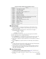
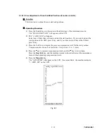
8.1.4.16 Display of the Equipment’s Log Information (Function code 80)
Function
The equipment may display its log information on the LCD.
Operating Procedure
(1) Press the
8
and
0
keys in this order in the initial stage of the maintenance mode.
The USB serial number appears on the LCD.
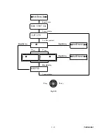
(2) Press the
Black Start
key. Each time the
Black Start
key is pressed, one of the
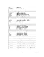
following log information items appears on the LCD in the order given below.
1) USB serial number
2) Page count, indicating how many pages the photosensitive drum has been printed
3) Total page count, indicating how many pages the equipment has been printed since
produced
4) Toner change count, indicating how many times toner replacement has been made
5) Copy page count, indicating how many copies have been made
6) PC print page count, indicating how many pages the equipment has been printed as
an output device of the connected PC
7) FAX page count, indicating how many received FAX pages have been printed
8) ADF jam count, indicating how many times a document jam has been occurred
9) ADF page count, indicating how many documents have been fed
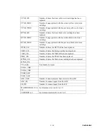
10) Error code of the most recent machine error *
1
11) Error code of the most recent communications error *
2
(3) To stop this operation and return to the equipment to the initial stage of the maintenance
mode, press the
Stop/Exit
key.
*
1
When you press the
Menu/Set
key while the MACHINE ERR error code is
displayed, the last error code is displayed. Each time the
Menu/Set
key is pressed,
up to the ten error codes are displayed one by one in reverse order.
*
2
When you press the
Menu/Set
key while the COMEER1 error is displayed, the last
error, the previous error, and the second previous error are displayed in turn. The
indication changes from COMEER1, COMEER2, to COMEER3.
Summary of Contents for MFC-9420CN
Page 1: ...Confidential FACSIMILE EQUIPMENT SERVICE MANUAL MODELS MFC 9420CN ...
Page 16: ...Confidential CHAPTER 1 PARTS NAMES FUNCTIONS ...
Page 22: ...Confidential CHAPTER 2 SPECIFICATIONS ...
Page 33: ...Confidential CHAPTER 3 THEORY OF OPERATION ...
Page 48: ...Confidential 3 1 4 CBV DBV Fig 3 16 Y M C K Fig 3 17 ...
Page 69: ...Confidential 3 3 5 Fig 3 35 ...
Page 73: ...Confidential 3 3 9 3 Interface Circuit Printer side Fig 3 38 ...
Page 82: ...Confidential CHAPTER 4 TRANSFER OF DATA LEFT IN THE MACHINE TO BE SENT FOR REPAIR ...
Page 85: ...Confidential 4 2 Cover page sample End page sample Fig 4 1 ...
Page 86: ...Confidential CHAPTER 5 DISASSEMBLY REASSEMBLY AND LUBRICATION ...
Page 94: ...Confidential 5 5 5 1 1 AC Cord 1 Disconnect AC cord from the machine Fig 5 1 AC cord Machine ...
Page 175: ...Confidential CHAPTER 6 ADJUSTMENTS AND UPDATING OF SETTINGS REQUIRED AFTER PARTS REPLACEMENT ...
Page 203: ...Confidential CHAPTER 7 CLEANING ...
Page 205: ...Confidential CHAPTER 8 MAINTENANCE MODE ...
Page 213: ...8 6 Confidential Fig 8 2 Scanning Compensation Data List a b c d e f g h i j k l m n q ...
Page 224: ...8 17 Confidential Cover page sample End page sample Fig 8 8 ...
Page 255: ...Confidential CHAPTER 9 ERROR INDICATION AND TROUBLESHOOTING ...
Page 279: ...Confidential 9 23 2 Image failure 1 2 3 4 5 6 7 8 9 10 11 12 13 14 ...
Page 280: ...Confidential 9 24 15 a 15 b 16 17 18 19 20 21 22 23 24 25 Fig 9 1 ...
Page 325: ...App 1 5 Confidential 6 Transfer Unit X X X X X X 7 1 2 3 Location SERIAL NO YEAR MONTH DATE ...
Page 398: ...B Power Supply PCB 100V 127V Confidential ...


