App.
4-40
Confidential
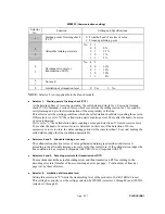
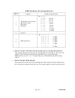
WSW36
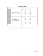
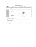
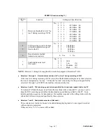
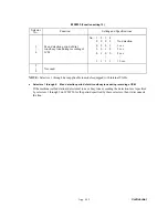
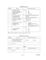
(Function setting 14)
Selector
No.
Function
Setting and Specifications
1
ECP mode*
(Not used.)
0:
ON
1:
OFF
2
Recovery from Inactive PC
Interface
(Not used.)
0:
Disable 1:
Enable
3
PC Power-off Recognition
Time
(Not used.)
0:
Normal 1:
Long
4 Not
used.
5
Escape from phase C
0: Yes
1: No
6
|
8
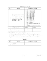
Extension of incoming calling
signal (CI) frequency band
specified by selectors 1
through 4 on WSW14
No. 6 7 8
0 0 0 : 0 (Ignored)
0 0 1 : 4 (448 Hz)
0 1 0 : 8 (244 Hz)
0 1 1 : 12 (162 Hz)
1 0 0 : 16 (122 Hz)
1 0 1 : 20 (97 Hz)
1 1 0 : 24 (81 Hz)
1 1 1 : 28 (69 Hz)
*ECP (Enhanced Capabilities Port)
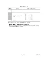
Selector 1: ECP mode (Not used.)
The ECP mode enhances the normal bidirectional communications between the machine and the
connected PC for higher transmission speed.
Selector 2: Recovery from Inactive PC Interface (Not used.)
If the machine recognizes via the STB signal line that the connected PC is powered off, it will turn
the PC interface outputs Low to protect the PC from hazards that could be caused by weak electric
current accidentally flown from the machine.
This selector determines whether or not the machine should recover from the inactive PC interface
to normal interfacing state upon receipt of data from the PC.
Selector 3: PC Power-off Recognition Time (Not used.)
This selector sets the time length from when the machine detects the PC powered off until it
recognizes the detected state as power-off.
If selector 2 is set to "0," it is recommended that selector 3 be set to "1"; otherwise, the machine
may mistakenly detect PC powered off.
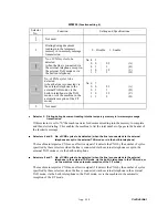
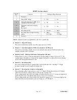
Selector 5: Escape from phase C
This selector determines whether or not the machine will escape from phase C when it detects an
RTC (Return to Control) in non-ECM mode or an RCP (Return to Control Partial page) in ECM
mode.
Summary of Contents for MFC-9420CN
Page 1: ...Confidential FACSIMILE EQUIPMENT SERVICE MANUAL MODELS MFC 9420CN ...
Page 16: ...Confidential CHAPTER 1 PARTS NAMES FUNCTIONS ...
Page 22: ...Confidential CHAPTER 2 SPECIFICATIONS ...
Page 33: ...Confidential CHAPTER 3 THEORY OF OPERATION ...
Page 48: ...Confidential 3 1 4 CBV DBV Fig 3 16 Y M C K Fig 3 17 ...
Page 69: ...Confidential 3 3 5 Fig 3 35 ...
Page 73: ...Confidential 3 3 9 3 Interface Circuit Printer side Fig 3 38 ...
Page 82: ...Confidential CHAPTER 4 TRANSFER OF DATA LEFT IN THE MACHINE TO BE SENT FOR REPAIR ...
Page 85: ...Confidential 4 2 Cover page sample End page sample Fig 4 1 ...
Page 86: ...Confidential CHAPTER 5 DISASSEMBLY REASSEMBLY AND LUBRICATION ...
Page 94: ...Confidential 5 5 5 1 1 AC Cord 1 Disconnect AC cord from the machine Fig 5 1 AC cord Machine ...
Page 175: ...Confidential CHAPTER 6 ADJUSTMENTS AND UPDATING OF SETTINGS REQUIRED AFTER PARTS REPLACEMENT ...
Page 203: ...Confidential CHAPTER 7 CLEANING ...
Page 205: ...Confidential CHAPTER 8 MAINTENANCE MODE ...
Page 213: ...8 6 Confidential Fig 8 2 Scanning Compensation Data List a b c d e f g h i j k l m n q ...
Page 224: ...8 17 Confidential Cover page sample End page sample Fig 8 8 ...
Page 255: ...Confidential CHAPTER 9 ERROR INDICATION AND TROUBLESHOOTING ...
Page 279: ...Confidential 9 23 2 Image failure 1 2 3 4 5 6 7 8 9 10 11 12 13 14 ...
Page 280: ...Confidential 9 24 15 a 15 b 16 17 18 19 20 21 22 23 24 25 Fig 9 1 ...
Page 325: ...App 1 5 Confidential 6 Transfer Unit X X X X X X 7 1 2 3 Location SERIAL NO YEAR MONTH DATE ...
Page 398: ...B Power Supply PCB 100V 127V Confidential ...


