Confidential
3 - 2 0
8 Drum
Cleaning
Transfer belt cleaning process means that the residual toner on the transfer belt is removed.
(1) Structure of transfer unit cleaner PU (Refer to Fig.3-23.)
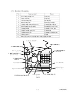
1) Transfer unit cleaner PU is located as shown in
Fig.3-9
.
2) Cleaning brush is a semiconductor type fur brush to clean the surface of transfer belt
as rotating. However, the cleaning brush stays away from the transfer belt while
imaging on the transfer belt.
3) Belt cleaning roller is positively biased by the positive voltage FCBV(V).
4) FCBV(V) is injected to the cleaning brush as well, and the cleaning brush is self-
biased by the resistance of brush.
5) Cleaning roller rotates as contacting to the belt cleaning brush.
(2) Process of transfer belt cleaning (Refer to Fig.3-23.)
1) There is the residual toner on the surface of transfer belt after the paper transfer
process.
2) Cleaning brush is positively self-biased. Cleaning brush has the negatively charged
residual toner fall off from the surface of transfer belt, and electrically absorbs the
residual toner into the belt cleaning brush.
3) Cleaning roller has been biased to the positive FCBV(V), the residual toner absorbed
into the cleaning brush is attracted by the positive FCBV(V) is adhered to the surface
of cleaning roller.
4) Waste toner adhering to the surface of cleaning roller PU is scavenged by the
cleaning blade and collected to the waste toner pack by the waste toner feeder.
Cleaning Brush
Cleaning Roller
Waste Toner Feeder
Claening Roller PU
Drum
Residual
Toner
Transfer Belt
FCBV
Fig. 3-23
Summary of Contents for MFC-9420CN
Page 1: ...Confidential FACSIMILE EQUIPMENT SERVICE MANUAL MODELS MFC 9420CN ...
Page 16: ...Confidential CHAPTER 1 PARTS NAMES FUNCTIONS ...
Page 22: ...Confidential CHAPTER 2 SPECIFICATIONS ...
Page 33: ...Confidential CHAPTER 3 THEORY OF OPERATION ...
Page 48: ...Confidential 3 1 4 CBV DBV Fig 3 16 Y M C K Fig 3 17 ...
Page 69: ...Confidential 3 3 5 Fig 3 35 ...
Page 73: ...Confidential 3 3 9 3 Interface Circuit Printer side Fig 3 38 ...
Page 82: ...Confidential CHAPTER 4 TRANSFER OF DATA LEFT IN THE MACHINE TO BE SENT FOR REPAIR ...
Page 85: ...Confidential 4 2 Cover page sample End page sample Fig 4 1 ...
Page 86: ...Confidential CHAPTER 5 DISASSEMBLY REASSEMBLY AND LUBRICATION ...
Page 94: ...Confidential 5 5 5 1 1 AC Cord 1 Disconnect AC cord from the machine Fig 5 1 AC cord Machine ...
Page 175: ...Confidential CHAPTER 6 ADJUSTMENTS AND UPDATING OF SETTINGS REQUIRED AFTER PARTS REPLACEMENT ...
Page 203: ...Confidential CHAPTER 7 CLEANING ...
Page 205: ...Confidential CHAPTER 8 MAINTENANCE MODE ...
Page 213: ...8 6 Confidential Fig 8 2 Scanning Compensation Data List a b c d e f g h i j k l m n q ...
Page 224: ...8 17 Confidential Cover page sample End page sample Fig 8 8 ...
Page 255: ...Confidential CHAPTER 9 ERROR INDICATION AND TROUBLESHOOTING ...
Page 279: ...Confidential 9 23 2 Image failure 1 2 3 4 5 6 7 8 9 10 11 12 13 14 ...
Page 280: ...Confidential 9 24 15 a 15 b 16 17 18 19 20 21 22 23 24 25 Fig 9 1 ...
Page 325: ...App 1 5 Confidential 6 Transfer Unit X X X X X X 7 1 2 3 Location SERIAL NO YEAR MONTH DATE ...
Page 398: ...B Power Supply PCB 100V 127V Confidential ...


