Confidential
3 - 2 2
3.2.3 Paper Transportation System
(1) Outline
This machine employs the automatic paper feeding with the paper tray.
When toner images are formed on the transfer belt through the operations of print system and
transfer system, a paper is fed by the paper feed roller and transported to the registration roller.
The transported paper is further transported to the transfer, fuser and exit part by the
registration roller synchronizing with the rotation of the transfer belt.
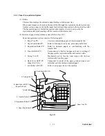
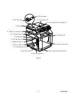
(2) Structure of paper transportation system (Refer to Fig.3-25.)
Paper transportation system consists of following parts.
1 Paper Tray PU:
Case to accommodate papers to be automatically fed.
2 Paper Feed Roller PU:
Roller to feed paper one by one, preventing multi-feed.
3 Registration Roller PU:
Roller to transport papers as synchronizing with the
transfer belt.
4 Transfer Roller PU:
Component to be built in the paper exit unit, consisting of
the paper guide, registration roller and transfer roller.
5 Fusing Unit FU:
Mechanical part to fuse the toner image with the heat
roller and fix it on the paper.
6
Back
Cover ASSY PU
(Paper Exit Unit):
Component to consist of the paper guide and paper exit
roller that exits the fusing-completed paper.
7 Exit Roller ASSY PU:
Roller to exit papers from of the machine.
Fig. 3-25
1. Paper Tray PU
2. Paper Feed Roller PU
3. Registration Roller PU
4. Transfer Roller PU
Transfer Belt
6.
Back
Cover ASSY PU
(Paper Exit Unit):
5. Fusing Unit FU
7. Exit Roller ASSY PU
Summary of Contents for MFC-9420CN
Page 1: ...Confidential FACSIMILE EQUIPMENT SERVICE MANUAL MODELS MFC 9420CN ...
Page 16: ...Confidential CHAPTER 1 PARTS NAMES FUNCTIONS ...
Page 22: ...Confidential CHAPTER 2 SPECIFICATIONS ...
Page 33: ...Confidential CHAPTER 3 THEORY OF OPERATION ...
Page 48: ...Confidential 3 1 4 CBV DBV Fig 3 16 Y M C K Fig 3 17 ...
Page 69: ...Confidential 3 3 5 Fig 3 35 ...
Page 73: ...Confidential 3 3 9 3 Interface Circuit Printer side Fig 3 38 ...
Page 82: ...Confidential CHAPTER 4 TRANSFER OF DATA LEFT IN THE MACHINE TO BE SENT FOR REPAIR ...
Page 85: ...Confidential 4 2 Cover page sample End page sample Fig 4 1 ...
Page 86: ...Confidential CHAPTER 5 DISASSEMBLY REASSEMBLY AND LUBRICATION ...
Page 94: ...Confidential 5 5 5 1 1 AC Cord 1 Disconnect AC cord from the machine Fig 5 1 AC cord Machine ...
Page 175: ...Confidential CHAPTER 6 ADJUSTMENTS AND UPDATING OF SETTINGS REQUIRED AFTER PARTS REPLACEMENT ...
Page 203: ...Confidential CHAPTER 7 CLEANING ...
Page 205: ...Confidential CHAPTER 8 MAINTENANCE MODE ...
Page 213: ...8 6 Confidential Fig 8 2 Scanning Compensation Data List a b c d e f g h i j k l m n q ...
Page 224: ...8 17 Confidential Cover page sample End page sample Fig 8 8 ...
Page 255: ...Confidential CHAPTER 9 ERROR INDICATION AND TROUBLESHOOTING ...
Page 279: ...Confidential 9 23 2 Image failure 1 2 3 4 5 6 7 8 9 10 11 12 13 14 ...
Page 280: ...Confidential 9 24 15 a 15 b 16 17 18 19 20 21 22 23 24 25 Fig 9 1 ...
Page 325: ...App 1 5 Confidential 6 Transfer Unit X X X X X X 7 1 2 3 Location SERIAL NO YEAR MONTH DATE ...
Page 398: ...B Power Supply PCB 100V 127V Confidential ...

