3-1
Confidential
CHAPTER 3 DISASSEMBLY AND ASSEMBLY
This chapter details procedures for disassembling and reassembling the machine together with related
notes. The disassembly order flow provided enables you to see at a glance the quickest way to get to
component(s) involved.
At the start of a disassembly job, you check the disassembly order flow that guides you through a
shortcut to the target components.
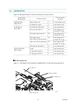
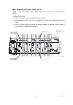
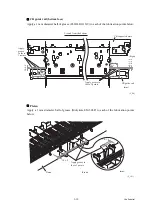
This chapter also covers screw tightening torques and lubrication points to which the specified
lubricants should be applied during reassembly jobs.
3.1
SAFETY PRECAUTIONS AND HANDLING NOTES
To prevent the creation of secondary problems by mishandling, observe the following
precautions during maintenance work.
(1) Be careful not to lose screws, washers, or other parts removed for parts replacement.
(2) When using soldering irons and other heat-generating tools, take care not to damage the
resin parts such as wires, PCBs, and covers.
(3) Static electricity charged in your body may damage electronic parts.
Before handling the PCBs, touch a metal portion of the machine to discharge static
electricity charged in your body. When transporting PCBs, be sure to wrap them in
conductive sheets.
When replacing the head/carriage unit, put on a grounding wrist band and perform the job
on a static mat. Also take care not to touch the conductor sections on the flat cables.
(4) Be sure to reinsert self-tapping screws correctly, if removed.
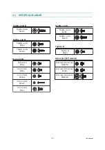
(5) Tighten screws to the torque values listed on the next page.
(6) When connecting or disconnecting cable connectors, hold the connector bodies not the
wires. If the connector has a lock, always slide the connector lock to unlock it.
(7) Before reassembly, apply the specified lubricant to the specified points. (Refer to
in this chapter.)
(8) After repairs, check not only the repaired portion but also that the connectors and other
related portions function properly before operation checks.
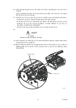
(9) Once the head/carriage unit prints, it will start head locking operation after five seconds
from the end of printing. The head locking operation will take 5 to 10 seconds. NEVER
unplug the power cord before the machine completes the head locking operation; doing so
will make the head/carriage unit unusable and require replacement with a new head/
carriage unit.
When you receive the machine from the user or when you pack it for sending it back to the
user, check the head locking state.
Before replacing parts or units, unplug the power cord and telephone line.
In particular, when having access to the power supply inside the machine, make sure that the
power cord is unplugged from the electrical outlet; when having access to the main PCB or
MJ PCB*, make sure that both the power cord and telephone line are unplugged from the
electrical outlet.
WARNING
WARNING
Summary of Contents for MFC-J6510DW
Page 15: ...xii Confidential ...
Page 16: ...xiii Confidential ...
Page 17: ...xiv Confidential ...
Page 18: ...xv Confidential ...
Page 19: ...xvi Confidential ...
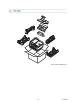
Page 128: ...3 3 Confidential 3 2 PACKING For models with paper tray 2 ...
Page 273: ...4 13 Confidential EXIT Adjust Check Pattern 1 ...
Page 274: ...4 14 Confidential EXIT Adjust Check Pattern 2 ...
Page 275: ...4 15 Confidential EXIT Adjust Check Pattern 3 ...
Page 276: ...4 16 Confidential KEISEN2 LF300 EXIT ADJUST PATTERN ...
Page 278: ...4 18 Confidential KEISEN GAP EXIT ADJUST PATTERN Line 1 Line 2 Line 3 ...
Page 280: ...4 20 Confidential Vertical Alignment Check Patterns ...
Page 283: ...4 23 Confidential Left Right and Bottom Margin Check Pattern ...
Page 286: ...4 26 Confidential Print Pattern for Creating Head Calibration Data ...
Page 302: ...4 42 Confidential ADF Copy Chart C A B D ...
Page 312: ...5 8 Confidential Print Pattern for Creating Head Calibration Data ...
Page 314: ...5 10 Confidential Scanning Compensation Data List ...
Page 317: ...5 13 Confidential Nozzle Test Pattern ...
Page 320: ...5 16 Confidential Configuration List ...
Page 337: ...5 33 Confidential EXIT Adjust Check Pattern 1 ...
Page 338: ...5 34 Confidential EXIT Adjust Check Pattern 2 ...
Page 339: ...5 35 Confidential EXIT Adjust Check Pattern 3 ...
Page 340: ...5 36 Confidential KEISEN2 LF300 EXIT ADJUST PATTERN ...
Page 346: ...5 42 Confidential Vertical Alignment Check Pattern ...
Page 349: ...5 45 Confidential Left Right and Bottom Margin Check Pattern ...
Page 383: ...6 4 Confidential Power supply PCB 100 V series ...
Page 384: ...6 5 Confidential Power supply PCB 200 V series ...
Page 385: ...6 6 Confidential Wiring diagrams ...


