3-118
Confidential
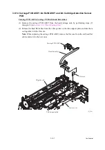
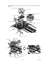
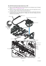
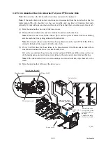
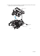
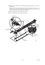
(3) Remove the SB timing belt from the left end of the engine unit.
(4) On the left end of the lower cover, release the four harnesses (paper feed motor harness, PF
encoder/PF sensor harness, registration sensor harness and switchback paper sensor
harness) from the cable guides.
(5) Remove the two screws from the engine unit.
(6) Lift the engine unit up and out of the lower cover in the direction of the arrow shown
below, holding the inner chute located beneath the CR guide rail.
Note:
Do not hold the CR guide rail.
Note:
Take care not to touch the PF encoder disk.
Note:
If the ink absorber box does not need to be replaced, be sure to take it out of the
lower cover together with the engine unit. If the main drain tube and air vent tube are
disconnected from the ink absorber box, they are reusable only one time by trimming their
ends vertically 10 mm with scissors clear and free of oil. Check that their cut surfaces are
free of oil. If it is the second time for those tubes to be disconnected, they need to be
replaced.
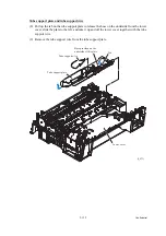
Note:
Do not place the engine unit directly on a flat surface; doing so may break the PF
encoder disk and gears. Be sure to place a support pad under the engine unit as shown
below.
(7) Take the flushing box and ink absorber felt out of the lower cover.
(3_088)
Engine unit
Taptite, cup B
M3x10
PF encoder disk
Paper feed
motor harness
Registration
sensor harness
PF encoder/
PF sensor harness
SB timing belt
Flushing box
Switchback paper
detection sensor
harness
(Front)
Lower cover
Ink absorber felt
Carriage motor harness
Purge cam switch harness
ASF motor harness
ASF encoder harness
ASF motor/encoder harness
PF encoder disk
Engine unit
Support pad
Summary of Contents for MFC-J6510DW
Page 15: ...xii Confidential ...
Page 16: ...xiii Confidential ...
Page 17: ...xiv Confidential ...
Page 18: ...xv Confidential ...
Page 19: ...xvi Confidential ...
Page 128: ...3 3 Confidential 3 2 PACKING For models with paper tray 2 ...
Page 273: ...4 13 Confidential EXIT Adjust Check Pattern 1 ...
Page 274: ...4 14 Confidential EXIT Adjust Check Pattern 2 ...
Page 275: ...4 15 Confidential EXIT Adjust Check Pattern 3 ...
Page 276: ...4 16 Confidential KEISEN2 LF300 EXIT ADJUST PATTERN ...
Page 278: ...4 18 Confidential KEISEN GAP EXIT ADJUST PATTERN Line 1 Line 2 Line 3 ...
Page 280: ...4 20 Confidential Vertical Alignment Check Patterns ...
Page 283: ...4 23 Confidential Left Right and Bottom Margin Check Pattern ...
Page 286: ...4 26 Confidential Print Pattern for Creating Head Calibration Data ...
Page 302: ...4 42 Confidential ADF Copy Chart C A B D ...
Page 312: ...5 8 Confidential Print Pattern for Creating Head Calibration Data ...
Page 314: ...5 10 Confidential Scanning Compensation Data List ...
Page 317: ...5 13 Confidential Nozzle Test Pattern ...
Page 320: ...5 16 Confidential Configuration List ...
Page 337: ...5 33 Confidential EXIT Adjust Check Pattern 1 ...
Page 338: ...5 34 Confidential EXIT Adjust Check Pattern 2 ...
Page 339: ...5 35 Confidential EXIT Adjust Check Pattern 3 ...
Page 340: ...5 36 Confidential KEISEN2 LF300 EXIT ADJUST PATTERN ...
Page 346: ...5 42 Confidential Vertical Alignment Check Pattern ...
Page 349: ...5 45 Confidential Left Right and Bottom Margin Check Pattern ...
Page 383: ...6 4 Confidential Power supply PCB 100 V series ...
Page 384: ...6 5 Confidential Power supply PCB 200 V series ...
Page 385: ...6 6 Confidential Wiring diagrams ...


