5-43
Confidential
5.1.4.21 Margin Adjustment in Borderless Printing
(Function code 66)
(User-accessible)
Function
This procedure adjusts the left, right and bottom margins for borderless printing. Print out a
margin check pattern, measure each margin, and enter the correction values.
Operating Procedure
Before starting the procedure below, be sure to set letter-size paper in the paper tray for
printing check patterns.
Printing the left, right and bottom margin check pattern
(1) Switch the machine to the maintenance mode.
(2) Connect the machine to your PC with a USB cable.
(3) On your PC, drag and drop the "mediaadj.prn" onto the Brother Maintenance USB Printer
driver icon in the Filedrgs window.
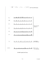
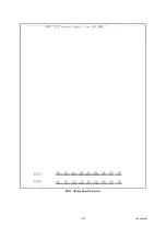
The machine displays the "RECEIVING DATA" on the LCD and prints out the "MEDIA
CHECK" pattern (see
for a sample printout). This is for checking the left and
right margins.
Tip:
Using Function code 61 (
Section 5.1.4.18 "Printout of PRN/JPEG Files in Memory
) also prints out the check pattern. After printing with a memory
card, be sure to remove the card and then proceed to the steps below.
Adjusting the left and right margins
(1) Measure the left and right margins on the printed pattern.
The upper row is printed in 600 dpi, and the lower row, in 1,200 dpi.
(Example) 600 dpi Left: 0.8 mm, Right: 1.1 mm
1,200 dpi Left: 0.9 mm, Right: 1.2 mm
If both of the left and right margins are within the range from 0.9 to 1.1 mm, no adjustment
is required. If not, go to step (2).
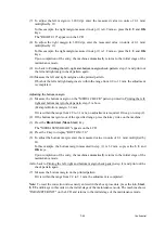
(2) If either one of the left and right margins is out of the specified range, press the
6
key twice
on the machine.
The "Select 66?" appears on the LCD.
(3) Press the
Black Start
(
Mono Start
) key.
The "MEDIA SENSOR ADJ" appears on the LCD.
(4) Press the
*
key to display "LEFT1 :10."
(5) To adjust the left margin in 600 dpi, enter the measured value (in units of 0.1 mm)
multiplied by 10.
In this example, the left margin measured in step (1) is 0.8 mm, so press the
0
,
8
, and
OK
keys.
NOTE:
In models having no
OK
key on the control panel, press the
PHOTO CAPTURE
key.
The "RIGHT1: 10" appears on the LCD.
(6) To adjust the right margin in 600 dpi, enter the measured value (in units of 0.1 mm)
multiplied by 10.
In this example, the right margin measured in step (1) is 1.1 mm, so press the
1
,
1
, and
OK
keys.
The "LEFT2: 10" appears on the LCD.
Summary of Contents for MFC-J6510DW
Page 15: ...xii Confidential ...
Page 16: ...xiii Confidential ...
Page 17: ...xiv Confidential ...
Page 18: ...xv Confidential ...
Page 19: ...xvi Confidential ...
Page 128: ...3 3 Confidential 3 2 PACKING For models with paper tray 2 ...
Page 273: ...4 13 Confidential EXIT Adjust Check Pattern 1 ...
Page 274: ...4 14 Confidential EXIT Adjust Check Pattern 2 ...
Page 275: ...4 15 Confidential EXIT Adjust Check Pattern 3 ...
Page 276: ...4 16 Confidential KEISEN2 LF300 EXIT ADJUST PATTERN ...
Page 278: ...4 18 Confidential KEISEN GAP EXIT ADJUST PATTERN Line 1 Line 2 Line 3 ...
Page 280: ...4 20 Confidential Vertical Alignment Check Patterns ...
Page 283: ...4 23 Confidential Left Right and Bottom Margin Check Pattern ...
Page 286: ...4 26 Confidential Print Pattern for Creating Head Calibration Data ...
Page 302: ...4 42 Confidential ADF Copy Chart C A B D ...
Page 312: ...5 8 Confidential Print Pattern for Creating Head Calibration Data ...
Page 314: ...5 10 Confidential Scanning Compensation Data List ...
Page 317: ...5 13 Confidential Nozzle Test Pattern ...
Page 320: ...5 16 Confidential Configuration List ...
Page 337: ...5 33 Confidential EXIT Adjust Check Pattern 1 ...
Page 338: ...5 34 Confidential EXIT Adjust Check Pattern 2 ...
Page 339: ...5 35 Confidential EXIT Adjust Check Pattern 3 ...
Page 340: ...5 36 Confidential KEISEN2 LF300 EXIT ADJUST PATTERN ...
Page 346: ...5 42 Confidential Vertical Alignment Check Pattern ...
Page 349: ...5 45 Confidential Left Right and Bottom Margin Check Pattern ...
Page 383: ...6 4 Confidential Power supply PCB 100 V series ...
Page 384: ...6 5 Confidential Power supply PCB 200 V series ...
Page 385: ...6 6 Confidential Wiring diagrams ...

