5-74
Confidential
Within 180 days from replacement of ink cartridges
Periodical reset purge (black and color) at 60-day intervals
Periodical suction purge (black) at 30-day intervals
After 180 days from replacement of ink cartridges
Periodical suction purge (black) at 30-day intervals
Periodical suction purge (color) at 60-day intervals
Periodical discharge purge (black and color) at 90-day intervals
Setting these selectors to "1, 0" (30 days (black), no purge (color)) disables the setting
made by selector 4.
Setting these selectors to "1, 1" (No purge (black and color)) disables the settings made by
selectors 4 and 8.
AMS05
(Printing assurance 3)
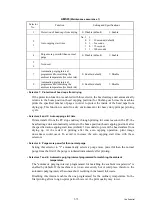
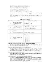
• Selector 1: Uneven printing correction for upper and lower ends of the nozzle
If performing the correction lowers the print quality due to wrong nozzle property data, set
this selector to "1" to disable the correction function.
• Selector 2: Switching of jam prevention mode for duplex printing
If a print margin is large for printing on large size paper in duplex printing, a jam may
occur during switchback of the recording paper. To prevent such a jam, set this selector to
"0" to make the print margin 22 mm. This function is available only in duplex copying.
• Selector 5: Jam reduction paper feed mode
Setting this selector to "1" lowers the paper feeding speed when the recording paper passes
along the star wheels for reduction of jams.
• Selectors 6 through 8: Adjustment of print head drive voltage rank
This selector regulates the print head drive voltage rank for adjusting the ink drop amount.
If the black section printed on glossy paper is greenish or the printed ink does not dry
quickly, increase the print head drive voltage rank to decrease the ink drop amount; if it is
reddish, decrease the rank to increase the ink drop amount.
Selector No.
Function
Setting and Specifications
1
Uneven printing correction for
upper and lower ends of the
nozzle
0: ON (default) 1: OFF
2
Switching of jam prevention
mode for duplex printing
0: Jam prevention mode
(Top and bottom margins: 22 mm)
1: Standard margin print mode
(Top and bottom margins: 3 mm)
3
4
Not used.
5
Jam reduction paper feed mode
0: Disable (default) 1: Enable
6
7
8
Adjustment of print head drive
voltage rank
No. 6
7
8
0
0
0: +0
1
0
0: -0
0
0
1: +1
0
1
0: +2
0
1
1: +3
1
0
1: -1
1
1
0: -2
1
1
1: -3
Summary of Contents for MFC-J6510DW
Page 15: ...xii Confidential ...
Page 16: ...xiii Confidential ...
Page 17: ...xiv Confidential ...
Page 18: ...xv Confidential ...
Page 19: ...xvi Confidential ...
Page 128: ...3 3 Confidential 3 2 PACKING For models with paper tray 2 ...
Page 273: ...4 13 Confidential EXIT Adjust Check Pattern 1 ...
Page 274: ...4 14 Confidential EXIT Adjust Check Pattern 2 ...
Page 275: ...4 15 Confidential EXIT Adjust Check Pattern 3 ...
Page 276: ...4 16 Confidential KEISEN2 LF300 EXIT ADJUST PATTERN ...
Page 278: ...4 18 Confidential KEISEN GAP EXIT ADJUST PATTERN Line 1 Line 2 Line 3 ...
Page 280: ...4 20 Confidential Vertical Alignment Check Patterns ...
Page 283: ...4 23 Confidential Left Right and Bottom Margin Check Pattern ...
Page 286: ...4 26 Confidential Print Pattern for Creating Head Calibration Data ...
Page 302: ...4 42 Confidential ADF Copy Chart C A B D ...
Page 312: ...5 8 Confidential Print Pattern for Creating Head Calibration Data ...
Page 314: ...5 10 Confidential Scanning Compensation Data List ...
Page 317: ...5 13 Confidential Nozzle Test Pattern ...
Page 320: ...5 16 Confidential Configuration List ...
Page 337: ...5 33 Confidential EXIT Adjust Check Pattern 1 ...
Page 338: ...5 34 Confidential EXIT Adjust Check Pattern 2 ...
Page 339: ...5 35 Confidential EXIT Adjust Check Pattern 3 ...
Page 340: ...5 36 Confidential KEISEN2 LF300 EXIT ADJUST PATTERN ...
Page 346: ...5 42 Confidential Vertical Alignment Check Pattern ...
Page 349: ...5 45 Confidential Left Right and Bottom Margin Check Pattern ...
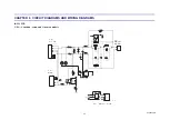
Page 383: ...6 4 Confidential Power supply PCB 100 V series ...
Page 384: ...6 5 Confidential Power supply PCB 200 V series ...
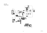
Page 385: ...6 6 Confidential Wiring diagrams ...

