5-68
Confidential
5.1.4.33 Assurance Mode Switch Setting
(Function code 88)
(User-accessible)
Function
The machine incorporates five assurance mode switches (AMS01 through AMS05) that are
firmware switches just as the ones described in
.
When the machine does not function normally because the usage environments or operating
conditions are not usual, the assurance mode switches provide workarounds to make the
machine usable by changing the machine settings to untypical ones.
The user is allowed to access the assurance mode switches under the guidance of service
personnel (e.g., by telephone).
The details about AMS01 through AMS05 are described on the following pages.
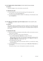
Operating Procedure
(1) Press the
8
key twice in the initial stage of the maintenance mode.
The machine displays "AMS00" on the LCD and becomes ready to accept an assurance
mode switch number.
(2) Enter the desired number from the assurance mode switch numbers (01 through 05).
The following appears on the LCD:
Selector 1
Selector 8
↓
↓
AMSXX = 0 0 0 0 0 0 0 0
(3) Use the and keys to move the cursor to the selector position to be modified.
NOTE:
In models with touch panel, if the , , , and keys are not displayed on the
software keypad, it is necessary to switch the software keypads between the numerical and
function keypads by pressing the
Scan
and
Copy
keys simultaneously.
(4) Enter the desired number (0 or 1) using the
0
and
1
keys.
(5) Press the
OK
key (
PHOTO CAPTURE
key for models without
OK
key). This operation
saves the newly entered selector values onto the EEPROM and readies the machine for
accepting an assurance mode switch number.
(6) Repeat steps (2) through (5) until the modification for the desired assurance mode switches
is completed.
(7) Press the
Stop/Exit
key to return the machine to the initial stage of the maintenance mode.
NOTES: •
To cancel this operation and return the machine to the initial stage of the
maintenance mode during the above procedure, press the
Stop/Exit
key.
•
If there is a pause of more than one minute after a single-digit number is entered for
double-digit assurance mode switch numbers, the machine will automatically
return to the initial stage of the maintenance mode.
•
Initializing the EEPROM with Function code 01 or 91 initializes the AMS switch
settings.
Summary of Contents for MFC-J6510DW
Page 15: ...xii Confidential ...
Page 16: ...xiii Confidential ...
Page 17: ...xiv Confidential ...
Page 18: ...xv Confidential ...
Page 19: ...xvi Confidential ...
Page 128: ...3 3 Confidential 3 2 PACKING For models with paper tray 2 ...
Page 273: ...4 13 Confidential EXIT Adjust Check Pattern 1 ...
Page 274: ...4 14 Confidential EXIT Adjust Check Pattern 2 ...
Page 275: ...4 15 Confidential EXIT Adjust Check Pattern 3 ...
Page 276: ...4 16 Confidential KEISEN2 LF300 EXIT ADJUST PATTERN ...
Page 278: ...4 18 Confidential KEISEN GAP EXIT ADJUST PATTERN Line 1 Line 2 Line 3 ...
Page 280: ...4 20 Confidential Vertical Alignment Check Patterns ...
Page 283: ...4 23 Confidential Left Right and Bottom Margin Check Pattern ...
Page 286: ...4 26 Confidential Print Pattern for Creating Head Calibration Data ...
Page 302: ...4 42 Confidential ADF Copy Chart C A B D ...
Page 312: ...5 8 Confidential Print Pattern for Creating Head Calibration Data ...
Page 314: ...5 10 Confidential Scanning Compensation Data List ...
Page 317: ...5 13 Confidential Nozzle Test Pattern ...
Page 320: ...5 16 Confidential Configuration List ...
Page 337: ...5 33 Confidential EXIT Adjust Check Pattern 1 ...
Page 338: ...5 34 Confidential EXIT Adjust Check Pattern 2 ...
Page 339: ...5 35 Confidential EXIT Adjust Check Pattern 3 ...
Page 340: ...5 36 Confidential KEISEN2 LF300 EXIT ADJUST PATTERN ...
Page 346: ...5 42 Confidential Vertical Alignment Check Pattern ...
Page 349: ...5 45 Confidential Left Right and Bottom Margin Check Pattern ...
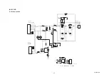
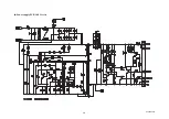
Page 383: ...6 4 Confidential Power supply PCB 100 V series ...
Page 384: ...6 5 Confidential Power supply PCB 200 V series ...
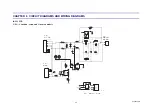
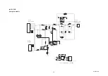
Page 385: ...6 6 Confidential Wiring diagrams ...

