background image

-33-

Main PC board

Power supply unit

Summary of Contents for PC-6000

Page 1: ...SERVICE MANUAL FOR COMPUTERIZED SEWING MACHINE PC6000 SUPER ACE I 9 1997 ...

Page 2: ...SMS 1 II DISASSEMBLING AND REASSEMBLING THE SEWING MACHINE 7 III HOW TO ADJUST MECHANICAL ELEMENTS 17 IV HOW TO ADJUST ELECTRONIC ELEMENTS 29 CAUTION 1 Always use rubber gloves when handling printed circuit boards and never touch the metal portion of a printed circuit board with bare hands 2 Keep your body earthed in order to avoid generating static electricity 3 Pack printed circuit boards in alu...

Page 3: ...CHANICAL CHART 2 2 POWER TRANSMISSION CHART 3 3 ELECTRONIC PARTS ARRANGEMENT CHART 4 4 CONTROL SYSTEM BLOCK DIAGRAM 4 5 MAIN MOTOR CONTROL 5 6 PATTERN GENERATOR 5 7 AUTOMATIC THREAD TENSION 5 8 OTHER ELECTRONIC COMPONENT FUNCTIONS 6 ...

Page 4: ... 2 1 MECHANICAL CHART ...

Page 5: ... 3 2 POWER TRANSMISSION CHART A Generating mechanism of needle bar thread take up lever and zigzag movements B Mechanism of feed dog and rotary hook movement ...

Page 6: ... 4 3 ELECTRONIC PARTS ARRANGEMENT CHART 4 CONTROL SYSTEM BLOCK DIAGRAM Control system block diagram ...

Page 7: ... the position of the needle while the needle is raised and stop it in the correct position and similarly they must move the position of the feed regulator while the needle is lowered Thus highly precise positioning and a fast response speed are required Because of this the feed pulse motor side feed pulse motor and a zigzag pulse motor were adopted and a simple open loop structure circuit was empl...

Page 8: ...s the operation for selecting the desired pattern and number Buttonhole stitch switch used to detect the edges of the buttonhole stitch by means of the buttonhole stitch presser foot and lever Buttonhole stitch lever switch used to detect whether the buttonhole stitch lever is raised or lowered Rotation sensor detects the drive timing of zigzag feed side feed and thread feed pulse motor and detect...

Page 9: ... 7 II DISASSEMBLING AND REASSEMBLING THE SEWING MACHINE 1 DISASSEMBLING AND REASSEMBLING THE OUTER PARTS AND MAIN PARTS 8 2 LEAD WIRE ARRANGEMENT 16 ...

Page 10: ...low by sliding it to the right 4 Remove the two screws securing the base cover slide the base cover to the left and then holding the front slide it to the left and out 5 Remove the screw securing the front cover near spool pin and loosen the two screws below jaw section on face plate side below free arm Open the front cover toward the front remove the four connectors and then the front cover 6 Rem...

Page 11: ...pull out the motor connector Remove the two screws and the main motor 13 Remove the screw and the board set plate D 14 Remove the side feed plate spring the three screws and the SPM holder 15 Remove the two screws and pull out the thread guide cover from the tension link 16 Remove the screw and the H block shaft holder assembly 17 Remove the three springs and the needle bar block assembly 18 Remov...

Page 12: ...lamp screw 22 Remove the presser bar by lifting it from above and the presser bar clamp 23 Remove the presser spring screw and the presser bar spring 24 Remove the presser lifter by pulling the presser lifting shaft straight out from the front 25 Pull the tension releaser plate out forward 26 Remove the screw and the thread take up shaft ...

Page 13: ...emove the metal presser screw and horizontal feed shaft bracket screw and then remove the horizontal feed assembly 32 Remove the two screws and FPM holder assembly 33 Remove the screw and the outer rotary hook assembly 34 Remove the two metal presser screws and remove the lower shaft assembly and timing belt 35 Remove the connector the two screws and the power supply unit assembly 36 Remove the th...

Page 14: ...o following illustrations and attach using the screw 41 Attach the FPM holder assembly using the two screws 42 Attach the horizontal feed shaft bracket using the screw and attach the horizontal feed assembly using the metal presser and screw 43 Insert the shaft of the feed rod into the feed block and catch the two feed rod tension springs 44 Attach the tension pulley holder using the screw 45 Atta...

Page 15: ...he collar and screw 50 Insert and attach the presser foot lifter using the presser lifter shaft 51 Insert and attach the presser bar into the presser bar clamp 52 Attach the presser bar spring onto the presser bar clamp 53 Attach the inner rotary hook bracket using the screw 54 Attach the thread cutter unit using the two screws ...

Page 16: ...d release link attach using the two screws 59 Attach the SPM holder assembly using the three screws and couple the horizontal feed shaft and side feed plate using the side feed plate spring 60 Attach the set plate D using the screws 61 Connect the motor connector attach the main motor using the two screws and catch the motor belt 62 Attach the bobbin winder assembly using the screw 63 Attach the h...

Page 17: ... 68 Connect the four connectors and attach the front cover using the three screws 69 Insert the base cover into the base plate and attach using the two screws 70 Attach the belt cover using the screw and fit the blind cap on 71 Attach the free arm cover using the screw 72 Attach the face plate using the screw ...

Page 18: ... 16 2 LEAD WIRE ARRANGEMENT ...

Page 19: ...21 9 PRESSER BAR HEIGHT 22 10 CHECKING DETECTION OF FABRIC THICKNESS 22 11 POSITION OF BUTTONHOLE SWITCH LEVER 23 12 BOBBIN WINDER 23 13 INNER ROTARY HOOK BRACKET POSITION 24 14 LARGE ONE POINT PATTERN SHAPE SOFT ADJUSTMENT 24 15 FEED ADJUSTMENT VERTICAL FEED 25 16 INNER ROTARY HOOK TENSION 25 17 NEEDLE THREADER 26 18 NEEDLE THREADER CHECKING THE HOOK POSITION IN HORIZONTAL DIRECTION 26 19 NEEDLE ...

Page 20: ...tal position of feed dog 21 The other test modes are used for factory adjustments 2 TENSION OF MOTOR BELT AND TIMING BELT STANDARD There should be a 4 6 mm slack in the motor belt when the center of the motor belt is pressed with a force of 200g There should be a 3 4 mm slack in the timing belt when it is pressed with a force of 200g ADJUSTMENT Timing belt 1 Loosen the screw of the belt adjusting ...

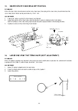
Page 21: ...ANCE BETWEEN THE NEEDLE AND THE ROTARY HOOK POINT STANDARD When test mode 5 is selected and the needle is raised 2 9 3 3 mm from its lowest position the rotary hook point should be positioned at the right side of the needle The clearance between the needle and the rotary hook point should be 0 1 mm or less and they should never touch each other ADJUSTMENT 1 Select test mode 5 2 Loosen the three sc...

Page 22: ...4 Move the needle bar vertically to adjust the clearance to between 1 0 1 4 mm 5 Tighten the screw of the needle bar block assembly NOTE The needle clamp should be parallel to the side of the needle plate If the needle bar is loose when you adjust the needle bar height it may result in sewing troubles 6 LOWER SHAFT 1 Attach the bushing presser L temporarily so as the center of lower shaft is posit...

Page 23: ...test mode 6 Loosen the screw securing the horizontal feed arm 7 Set the clearance between the feed dog and needle plate to 0 5 to 1 0 8 Tighten the screw securing the horizontal feed arm 9 After adjusting press the thread cut button and confirm that the thread cutter operates correctly If the thread cutter does not operate readjust the feed dog slightly to the back 8 HEIGHT OF FEED DOG STANDARD Wh...

Page 24: ...ETECTION OF FABRIC THICKNESS STANDARD When the fabric thickness is set to 0 mm and 3 mm in test mode 2 the buzzer should sound twice if operation is normal ADJUSTMENT 1 Select test mode 2 2 Install the J presser foot and then lower the presser foot and set the needle bar to the lowest position 3 Press 0 mm on the display The buzzer should sound twice 4 Insert a spacer with a thickness of 3 mm bene...

Page 25: ...N WINDER STANDARD The thread should be wound parallel to the bobbin and around about 85 90 of the bobbin at low speed The clearance between the bobbin winder switch and the bobbin winder assembly should be 0 5 1 0 mm ADJUSTMENT 1 Loosen the bobbin winding guide screw 2 Adjust the bobbin thread amount so that the thread is evenly wound around the bobbin by moving the bobbin winding guide vertically...

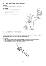
Page 26: ...ertically and or horizontally NOTE Surface A of the inner rotary hook bracket should be perpendicular to the feeding direction 3 Tighten the screw of the inner rotary hook bracket 14 LARGE ONE POINT PATTERN SHAPE SOFT ADJUSTMENT STANDARD When 3 pattern adjustment is selected in the test mode and the start button is pressed the vertical and horizontal separation of the pattern outline shape should ...

Page 27: ...g the pulse motor 16 INNER ROTARY HOOK TENSION STANDARD While slowly pulling polyester thread 60 using a tension gauge inner rotary hook tension should be 10 12g The difference between this and the tension for silk thread 80 should be 2 3g ADJUSTMENT 1 Pass polyester thread 60 through the inner rotary hook correctly and pull it using the tension gauge 2 Adjust the tension by turning the screw to e...

Page 28: ...er may be broken rendering it unusable Besides this it may cause the needle to break which could result in injury 7 If a 9 needle is used the variation in needle precision may result in the needle being slightly difficult to thread 8 Needle should be located above needle plate by more than 8 mm for threading 9 Needle threader does not work when you use the side cutter Thread the needle before atta...

Page 29: ...y up so that the guide is fits into the groove 20 NEEDLE THREADER CHECKING THE HOOK IN STANDARD POSITION STANDARD 1 The clearance between the top of hook and the top of needle eye is 0 mm 2 Threading is possible when needle is located higher than 8 mm from the needle plate CHECK refer to illustration Case A Hook position is too high Hook hits needle and cannot go through needle eye Case B Hook pos...

Page 30: ...and b are not parallel the needle threader will not be held by the needle threader position setter refer to Fig 1 the hook will not enter the eyelet of the needle hook will not move and the needle will not be threaded when the needle threader lever is lowered In this case loosen the screw securing the needle threader position setter and turn the needle threader position setter slightly to the left...

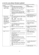
Page 31: ... 6 Correct patterns are not created 31 7 Buttonholes are not stitched correctly 31 8 Manual operation of feed and zigzag pulse motors is not possible 31 9 Vertical movement of needle bar and backstitch operation are abnormal 31 10 Foot controller does not operate normally when depressed 31 11 Thread tension is not correct 32 12 Needle bar release mechanism does not operate correctly 32 13 Thread c...

Page 32: ...edle position 3 Is a fuse blown 4 Is the voltage between pins 4 5 normal when the connector CN13 which is output from the power supply board is disconnected Between 4 5 20 30 VDC 5 Others 1 Replace the pulse motor which shows an abnormality 2 Replace NP board assembly 3 Replace fuse after correcting defect that caused fuse to blow 4 Replace power supply unit assembly 5 Replace main PC board assemb...

Page 33: ...er is pulled forward 1 W or less Buttonhole lever is pushed back 1 W or less 4 Others 1 Check stitch foot 2 Adjust button hole lever or replace BH switch assembly 3 Adjust button hole lever or replace BH switch assembly 4 Replace main PC board assembly 8 Manual operation of feed and zigzag pulse motors is not possible 1 Do manual keys of feed and zigzag pulse motors turn off and on normally and do...

Page 34: ...2 Replace F pulse motor or FPM lead wire assembly 3 Replace main PC board assembly 14 Display does not appear clearly 1 Is the voltage between pins 8 7 of the connector CN9 for LCD module 5 to 10VDC 2 Others 1 Replace main PC board assembly 2 Replace LCD module or main PC board assembly 15 The LCD light does not light 1 Is the voltage between pins 4 5 20 to 30 VDC when the connector CN7 which is o...

Page 35: ... 33 Main PC board Power supply unit ...

Page 36: ... 34 LCD unit Other PC boards 985 ...

Page 37: ... 35 PC6000 SUPER ACE I H7060087 ...

Reviews: