-15-
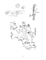
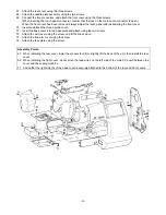
48. Attach the thread take-up shaft using the screw.
49. Insert the tension plate.
50. Attach the presser spring using the collar and screw.
51. Insert and attach the presser foot lifter using the presser lifter shaft.
52. Insert and attach the presser bar into the presser bar clamp.
53. Attach the presser bar spring onto the presser bar clamp.
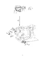
54. Attach the inner rotary hook rotation prevention plate using the screw.
55. Attach the thread cutter unit using the two screws.
Assembly Points
48. The screw (48) used to install the thread take-up lever shaft should have a nominal length of 14 mm.
*
The thread take-up lever shaft should be installed so that there is no gap between the right side of the thread
take-up and the stop ring. If there is a large gap, the right and left clearance may generate an irregular noise
(thread take-up lever noise).
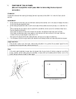
54. Install the inner rotary hook bracket assembly. (Firmly tighten the screw to make no space between (D) and
the arm so that the inner rotary hook bracket assembly does not rotate.)
*
After the inner rotary hook bracket assembly is installed, adjust the position where rotation is prevented.
(Refer to (A).)
*
If there is a small rotation prevention amount, the inner rotary hook may slip and start rotating causing
damage to the inner rotary hook or breaking the needle.
55. Before installing the thread cutting assembly, move the thread cutter cam so that its notch faces the front (B) of
the sewing machine.
55. Thread cutting assembly installation procedure
(1) Insert the projection (C) on the cutter unit into the arm guide hole.
(Insert the projection while checking that the inner rotary hook is correctly positioned.)
(2) Move the thread cutting assembly toward the right without bending the lower thread guide arm assembly to
install it.
*
After installing the thread cutting assembly, perform the following procedure to check that the movable blade
operates correctly.
(1) With the lever pin pressed in by hand, turn the balance wheel by hand to begin operating the movable blade.
(2) When the movable blade is at its rightmost position, release the lever pin and turn the balance wheel, then
check that the movable blade lightly returns to its previous position.
*
If the movable blade does not operate correctly, loosen the screw (55), move the thread cutting assembly
forward and backward, then move the unit toward the right and tighten the screw.
Summary of Contents for PC8200 SUPER GALAXIE 2000
Page 1: ...SERVICE MANUAL FOR COMPUTERIZED SEWING MACHINE PC8200 SUPER GALAXIE 2000 9 1997 ...
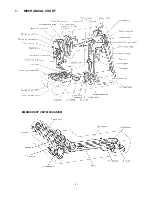
Page 4: ... 2 1 MECHANICAL CHART EMBROIDERY UNIT MECHANISM ...
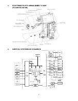
Page 6: ... 4 3 ELECTRONIC PARTS ARRANGEMENT CHART PC 8200 Model 985 4 CONTROL SYSTEM BLOCK DIAGRAM ...
Page 16: ... 14 ...
Page 18: ... 16 ...
Page 20: ... 18 ...
Page 23: ... 21 2 LEAD WIRE ARRANGEMENT PC 8200 Model 985 ...
Page 53: ... 51 Main PC board Power supply unit ...
Page 54: ... 52 LCD unit Other PC boards 985 ...
Page 55: ... 53 PC8200 SG2000 H7070093 ...

