-30-
8.
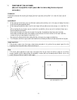
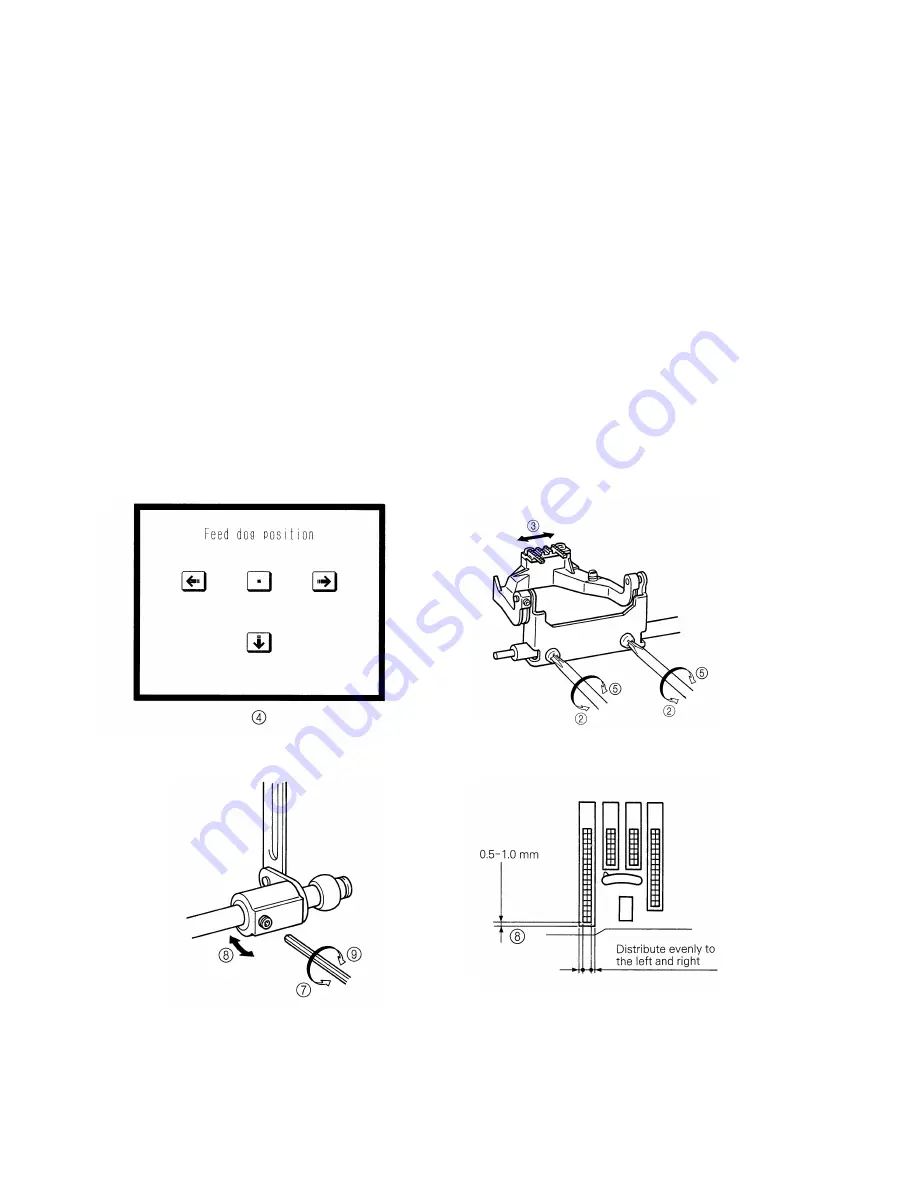
FRONT/BACK, LEFT/RIGHT POSITION OF FEED DOG
STANDARD
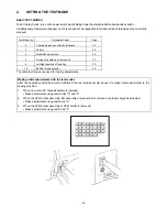
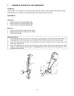
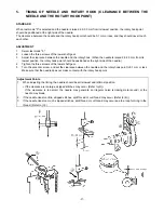
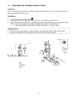
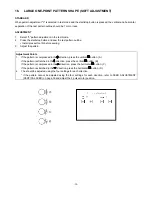
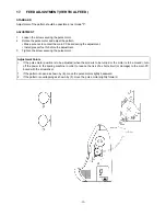
When test mode "6" is selected, move the feed dog front/back and left/right. At this time, the feed dog should not
contact the needle plate.
When the front/back position is the maximum feed amount, the clearance between the feed dog and needle plate at
the feed start position (when feed dog is at very front) should be 0.5 to 1.0. (Refer to illustration)
ADJUSTMENT
1. Select test mode "6".
2. Loosen the screw securing the horizontal feed plate.
3. Align the feed dog’s left / right position.
4. In the test mode, align the feed dog’s left/right position.
5. Tighten the screw securing the horizontal feed plate.
6. Move to the feed start position in the test mode.
7. Loosen the screw securing the horizontal feed arm.
8. Set the clearance between the feed dog and needle plate to 0.5 to 1.0.
9. Tighten the screw securing the horizontal feed arm.
10. After adjusting, press the thread cut button, and confirm that the thread cutter operates correctly. If the thread
cutter does not operate, readjust the feed dog slightly to the back.
Summary of Contents for PC8200 SUPER GALAXIE 2000
Page 1: ...SERVICE MANUAL FOR COMPUTERIZED SEWING MACHINE PC8200 SUPER GALAXIE 2000 9 1997 ...
Page 4: ... 2 1 MECHANICAL CHART EMBROIDERY UNIT MECHANISM ...
Page 6: ... 4 3 ELECTRONIC PARTS ARRANGEMENT CHART PC 8200 Model 985 4 CONTROL SYSTEM BLOCK DIAGRAM ...
Page 16: ... 14 ...
Page 18: ... 16 ...
Page 20: ... 18 ...
Page 23: ... 21 2 LEAD WIRE ARRANGEMENT PC 8200 Model 985 ...
Page 53: ... 51 Main PC board Power supply unit ...
Page 54: ... 52 LCD unit Other PC boards 985 ...
Page 55: ... 53 PC8200 SG2000 H7070093 ...

