-42-
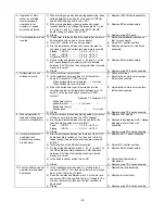
22.
NEEDLE THREADER
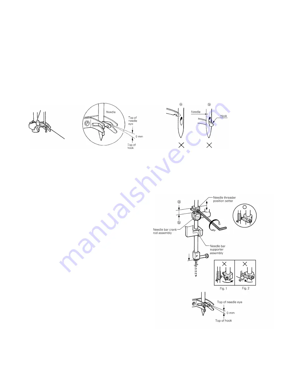
(CHECKING THE HOOK IN STANDARD POSITION)
STANDARD
1.
The clearance between the top of hook and the top of needle eye is 0 mm.
2.
Threading is possible when needle is located higher than 8 mm from the needle plate.
CHECK (refer to illustration)
Case A
Hook position is too high. (Hook hits needle and cannot go through needle eye.)
Case B
Hook position is too low. (Hook goes through needle eye but it catches bottom part of needle eye.)
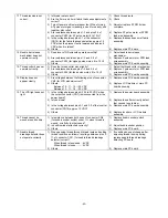
23.
NEEDLE THREADER
(CHECKING THE HOOK POSITION IN VERTICAL DIRECTION)
Case A (Hook point is too high)
1.
Remove face plate and loosen the screw.
2.
Adjust needle threader position setter slightly down and
check that the clearance between the top of hook
and top of needle eye is 0 mm.
3.
Check that the needle threader position setter (a) and
the needle bar crank rod assembly (b) is parallel.
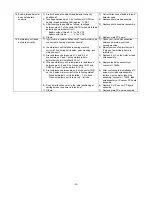
Case B (Hook point is too low)
Adjust needle threader position setter slightly up and check
the clearance between the top of hook and top of needle eye
is 0 mm.
In case part (a) and part (b) is not parallel or the hook does
not work, readjust needle threader by loosening the screw.
If (a) and (b) are not parallel, the needle threader will not be
held by the needle threader position setter (refer to Fig. 1),
the hook will not enter the eyelet of the needle (hook will not
move) and the needle will not be threaded when the needle
threader lever is lowered. In this case, loosen the screw
securing the needle threader position setter and turn the
needle threader position setter slightly to the left to make it
parallel.
In addition, if the needle threader position setter is turned too
far so that it is still not parallel too left, it may hit other parts,
causing damage (refer to Fig. 2). If a part is damaged, it
must be replaced. If no part is damaged, loosen the screw
securing the needle threader position setter and turn the
needle threader position setter slightly to the right to make it
parallel.
Summary of Contents for PC8200 SUPER GALAXIE 2000
Page 1: ...SERVICE MANUAL FOR COMPUTERIZED SEWING MACHINE PC8200 SUPER GALAXIE 2000 9 1997 ...
Page 4: ... 2 1 MECHANICAL CHART EMBROIDERY UNIT MECHANISM ...
Page 6: ... 4 3 ELECTRONIC PARTS ARRANGEMENT CHART PC 8200 Model 985 4 CONTROL SYSTEM BLOCK DIAGRAM ...
Page 16: ... 14 ...
Page 18: ... 16 ...
Page 20: ... 18 ...
Page 23: ... 21 2 LEAD WIRE ARRANGEMENT PC 8200 Model 985 ...
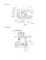
Page 53: ... 51 Main PC board Power supply unit ...
Page 54: ... 52 LCD unit Other PC boards 985 ...
Page 55: ... 53 PC8200 SG2000 H7070093 ...


