-49-
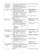
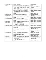
11. Thread tension is not
correct.
1) Is thread route correct?
2) Are the 0 mm and 3 mm fabric thickness adjustments
correct?
3) Turn off power and lower presser foot. When turning
AT pulse motor gear manually, does it turn easily, and
together with roller?
4) Are resistances between pins 1-3 and pins 2-4 of
connector CN12 (for AT pulse motor) 8 to 10
W
?
5) Is the voltage between pins 2-1 of the connector
(CN14) for the fabric thickness detection approx.1.5
VDC when the presser foot is lowered and approx.4
VDC when it is raised?
6) Others
1) Check thread route.
2) Check.
3) Adjust or replace ATPM holder
complete.
4) Replace AT pulse motor or ATPM
lead wire assembly.
5) Replace thickness sensor of fabric
assembly.
6) Replace main PC board.
12. Needle bar release
mechanism does not
operate correctly.
1) Does lever of NR solenoid operate smoothly?
2) Are resistances between pins 1-3 and 2-4 of
connector CN13 (for zigzag pulse motor) 8 to 10
W
?
3) Others
1) Adjust needle bar release
mechanism.
2) Replace Z pulse motor or ZPM lead
wire assembly.
3) Replace main PC board assembly.
13. Thread cutter does not
operate correctly.
1) Does the thread cutter move lightly?
2) Are resistances between pins 1-3 and 2-4 of
connector CN16 (for feed pulse motor) 8 to 10
W
?
3) Others
1) Adjust the thread cutter mechanism.
2) Replace F pulse motor or FPM lead
wire assembly.
3) Replace main PC board assembly.
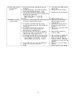
14. Display does not
appear clearly.
1) Are voltages between the following pins of connector
CN5 (for LCD module)correct?
2) Others
Between 12 - 11 - 16 - - 22 VDC
Between 13 - 11 - 16 - - 22 VDC
1) Replace main PC board assembly.
2) Replace LCD module or main PC
board assembly.
15. The LCD light does not
light.
1) Is the voltage between pins 4-5 24 to 30 VDC when
the output connector (CN7) is disconnected from the
power board ?
2) Is fuse blown?
3) Is the voltage between pins 3-1 and 3-2 of the inverter
connector (CN18) approx. 12 VDC?
4) Others
1) Replace the power board assembly.
2) Replace fuse after correctly defect
that caused fuse to blow.
3) Replace main PC board assembly.
4) Replace inverter or LCD module
assembly.
16. Thread cannot be
wound around bobbin.
1) Is resistance between both ends of connector CN6
(for bobbin winder switch) under 1
W
when thread is
wound, or infinity in other cases?
2) Is bobbin winder attached correctly?
3) Others
1) Replace bobbin winder switch
assembly.
2) Adjust bobbin winder position.
3) Replace main PC board.
17. Needle thread
breakage detector does
not operate correctly.
1) When passing thread through thread route and setting
thread condition as follows, is voltage between pins 2-
11 of connector CN11 (for needle thread breakage
detector) correct?
When thread is tensioned... 6 VDC
When thread is loose.......... 5 VDC
2) Others
1) If condition does not change after
adjusting thread take-up spring,
replace needle thread breakage
detecting PC board.
2) Replace main PC board.
Summary of Contents for PC8200 SUPER GALAXIE 2000
Page 1: ...SERVICE MANUAL FOR COMPUTERIZED SEWING MACHINE PC8200 SUPER GALAXIE 2000 9 1997 ...
Page 4: ... 2 1 MECHANICAL CHART EMBROIDERY UNIT MECHANISM ...
Page 6: ... 4 3 ELECTRONIC PARTS ARRANGEMENT CHART PC 8200 Model 985 4 CONTROL SYSTEM BLOCK DIAGRAM ...
Page 16: ... 14 ...
Page 18: ... 16 ...
Page 20: ... 18 ...
Page 23: ... 21 2 LEAD WIRE ARRANGEMENT PC 8200 Model 985 ...
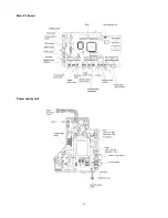
Page 53: ... 51 Main PC board Power supply unit ...
Page 54: ... 52 LCD unit Other PC boards 985 ...
Page 55: ... 53 PC8200 SG2000 H7070093 ...


