- 16 -
Assembly
40. Align hole of presser foot lift with hole in the arm bed, attach presser foot lift shaft so that it catches onto
guide of presser foot lift.
41. Attach thread tension plate B to arm bed and attach spring.
42. While attaching spring and presser bar bracket, insert presser bar from the top. Loosely fasten screw on
presser bar bracket.
43. Attach drop holder assembly with 2 screws.
44. Use one screw to attach bobbin winder assembly.
45.
-1. While attaching bobbin winder spring between bobbin winder plate and bobbin winder spring plate, screw on
bobbin winder spring plate.
-2. Screw on set plate.
46. Use 2 screws to attach ZPM assembly (without Z gear).
47. Attach upper shaft assembly using two bushing presser, with one screw each.
48. Attach thread take-up lever shaft to thread take-up lever. Attach to arm bed using presser plate and screw.
49. Attach shaft of needle bar crank to groove of thread take-up lever and thread take-up crank. Fix in place with
thread take-up crank screw.
50. After setting needle bar supporter shaft into hole in arm bed, attach needle bar clamp shaft to needle bar
crank rod and attach needle bar supporter assembly. Attach spring between needle bar supporter and arm
bed.
51. Attach needle bar supporter arm to needle bar supporter pin.While keeping held in position, attach H shaft
holder with screw.
52. Line up indicator marks on ZPM gear and Z gear (see page 42 of adjustment procedures), attach Z gear
(with zigzag connecting rod attached) and fasten on with retaining ring.
53. Attach zigzag nut to zigzag connecting rod, screw zigzag connecting rod and needle bar supporter together.
Assembly Points
41. Make sure that spring is lined up in correct direction.
42. Take care that the spring doesn’t fly across the room.
47. After fastening screws, check to make sure the upper shaft rotates freely.
49. When D-cut face of needle bar crank shaft is in uppermost position of thread take-up crank, attach so that
it comes toward the front. While gently pushing needle bar crank with your hand, secure front with screw.
Then fasten top screw. After fastening screws, check to make sure that upper shaft rotates as smoothly
as it did before screws were fastened.
51. Attach H shaft holder with arm bed pin in center of oblong hole. (see diagram A)
Summary of Contents for PE-300S
Page 1: ... 2 1999 ...
Page 4: ... 2 1 MECHANICAL CHART EMBROIDERY UNIT MECHANISM ...
Page 6: ... 4 3 ELECTRONIC PARTS ARRANGEMENT CHART ...
Page 7: ... 5 4 CONTROL SYSTEM BLOCK DIAGRAM ...
Page 11: ... 9 9 1 1 9 9 8 7 7 3 3 6 6 2 2 3 1 1 9 5 5 5 ...
Page 13: ... 11 12 11 17 20 20 15 16 19 20 18 13 14 10 10 ...
Page 15: ... 13 25 2 25 1 23 36 29 29 37 32 22 22 24 24 27 27 30 30 31 31 33 33 34 32 28 36 35 26 ...
Page 17: ... 15 39 39 38 ...
Page 19: ... 17 Diagram A 45 1 45 2 42 53 48 52 49 50 43 42 41 44 47 47 46 40 51 ...
Page 21: ... 19 Diagram A 55 60 56 54 58 64 64 65 61 61 59 59 54 57 ...
Page 23: ... 21 diagram A 74 69 69 68 69 75 73 72 70 67 67 ...
Page 25: ... 23 77 78 84 68 84 78 78 79 86 86 84 ...
Page 27: ... 25 5 3 2 2 2 2 3 4 1 5 ...
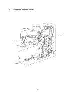
Page 28: ... 26 3 LEAD WIRE ARRANGEMENT ...
Page 57: ...PE 300S H8080132 ...


