- 31 -
4.
TIMING OF ROTATION SHUTTER AND UP-DOWN FEED CAM
STANDARD
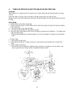
When needle bar is in highest position, foundation hole of vertical shaft pulley should be facing front of sewing
machine.
At this time, base line of outer rotary hook pulley should also be facing front of sewing machine.
Phases of base line of rotation shutter even with screw hole and foundation hole of vertical shaft pulley should be
the same.
ADJUSTMENT
•
Vertical shaft and outer rotary hook pulleys
1.
Position so that base lines of vertical shaft and outer rotary hook pulleys are facing front of sewing machine.
Attach timing belt.
2.
Loosen both screws of the upper shaft gear.
3.
Turn pulley to raise needle bar to its uppermost position.
4.
Make sure that vertical shaft and outer rotary hook pulleys are positioned as indicated in 1. Then tighten both
upper shaft gear screws.
* After completing adjustments, make absolutely sure to check the backlash of the upper and vertical shaft
gears.
•
Rotation shutter
1.
Loosen rotation shutter screw.
2.
Adjust phases of base line of rotation shutter even with screw hole and foundation hole of vertical shaft
pulley.
3.
Tighten rotation shutter screw.
* Use only 2-4kg-cm of torque when tightening rotation shutter screw. Applying too much pressure could
wear out grooves in top of screw, making it impossible to fasten securely.
base line
foundation
hole
base line
Summary of Contents for PE-300S
Page 1: ... 2 1999 ...
Page 4: ... 2 1 MECHANICAL CHART EMBROIDERY UNIT MECHANISM ...
Page 6: ... 4 3 ELECTRONIC PARTS ARRANGEMENT CHART ...
Page 7: ... 5 4 CONTROL SYSTEM BLOCK DIAGRAM ...
Page 11: ... 9 9 1 1 9 9 8 7 7 3 3 6 6 2 2 3 1 1 9 5 5 5 ...
Page 13: ... 11 12 11 17 20 20 15 16 19 20 18 13 14 10 10 ...
Page 15: ... 13 25 2 25 1 23 36 29 29 37 32 22 22 24 24 27 27 30 30 31 31 33 33 34 32 28 36 35 26 ...
Page 17: ... 15 39 39 38 ...
Page 19: ... 17 Diagram A 45 1 45 2 42 53 48 52 49 50 43 42 41 44 47 47 46 40 51 ...
Page 21: ... 19 Diagram A 55 60 56 54 58 64 64 65 61 61 59 59 54 57 ...
Page 23: ... 21 diagram A 74 69 69 68 69 75 73 72 70 67 67 ...
Page 25: ... 23 77 78 84 68 84 78 78 79 86 86 84 ...
Page 27: ... 25 5 3 2 2 2 2 3 4 1 5 ...
Page 28: ... 26 3 LEAD WIRE ARRANGEMENT ...
Page 57: ...PE 300S H8080132 ...


