II-1
CHAPTER II
THEORY OF OPERATION
2.1
OUTLINE OF MECHANISMS
2.1.1
Print Mechanism
Structure of Thermal Head
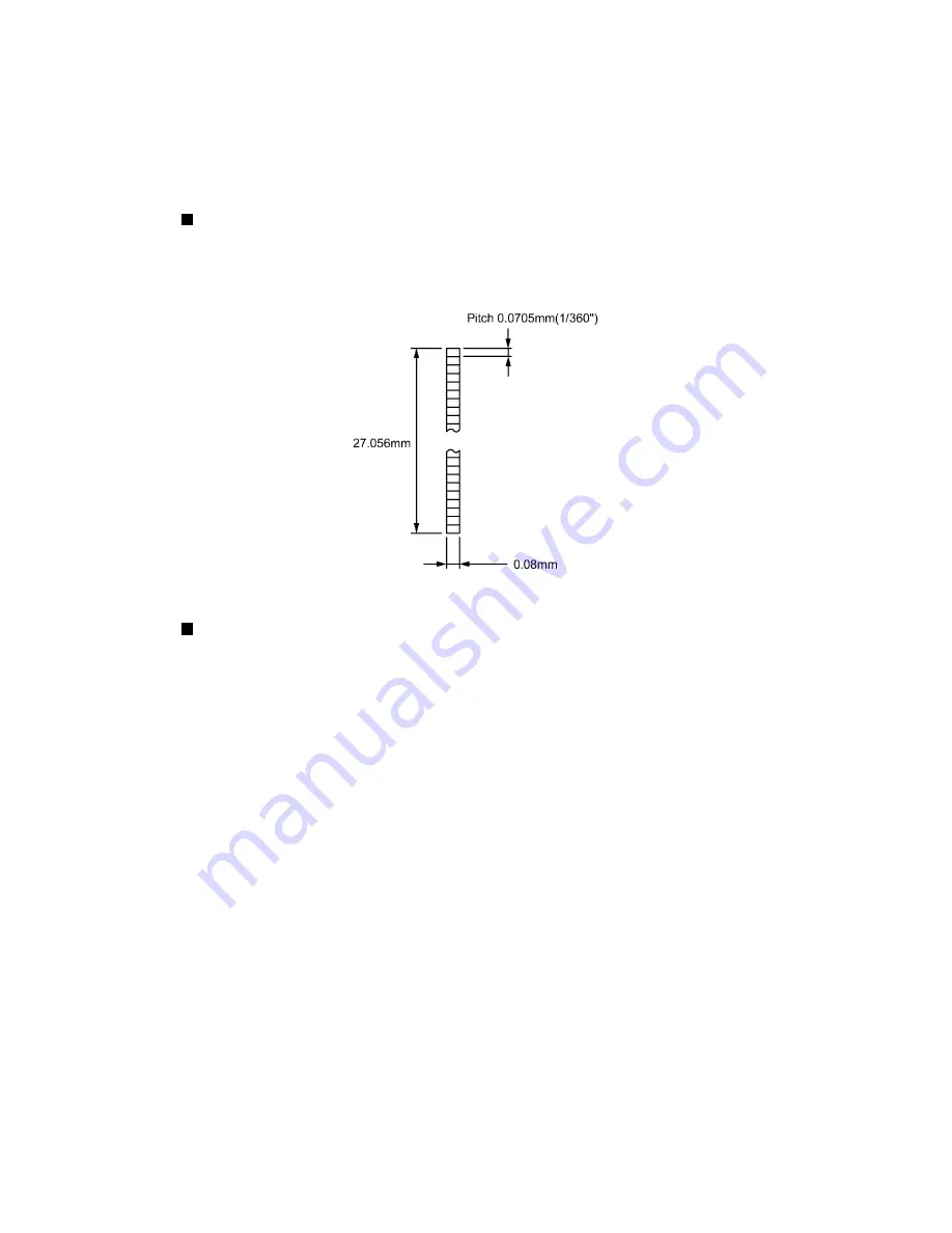
This machine uses thermal transfer printing. The thermal print head has a heat generator
consisting of 384 heating elements that are vertically aligned as shown in Fig. 2.1-1. Each
heating element is 0.08 mm wide by 0.0545 mm height (0.0705 mm per pitch).
Fig. 2.1-1 Heat Generator of the Thermal Head
Printing Process
In printing process, the cylindrical rubber platen is pressing the tape(*) and ink ribbon(**) against
the thermal print head. The heat generator divided into 384 elements on the thermal print head
is impressed selectively in this process. Principle of printing varies depending on whether the
heat sensitive tape cassette is used or not.
*
Laminate tape when using laminated tape cassettes.
Non-laminated tape when using non-laminated tape cassettes.
Instant lettering tape when using instant lettering tape cassettes.
Iron-on transfer tape when using iron-on transfer tape cassettes.
Cloth tape when using cloth tape cassettes.
Thermal tape when using AV (Avery) labels cassettes.
** When using AV labels cassettes or stamp tape cassettes, no ink ribbon is sandwiched.
[For tape cassettes except stamp tape cassettes and AV labels cassettes]
If the selected heating element(s) generates heat, the ink on the sandwiched ribbon will be
melted and transferred to the tape, producing a dot(s) on the tape. The ink ribbon and the tape
are advanced and then the next heating cycle is repeated, thus forming a character on the tape.
[For AV labels cassettes]
If the selected heating element(s) generates heat, the thermal tape develops itself to produce a
dot on the tape. The tape is advanced and the next heating cycle is repeated, thus forming a
character on the tape.
Summary of Contents for PT-9500PC - P-Touch 9500pc B/W Thermal Transfer Printer
Page 1: ...SERVICE MANUAL MODEL PT 9500PC ...
Page 2: ...SERVICE MANUAL MODEL PT 9500PC ...
Page 86: ...IV 10 3 The LED does not turn on 4 No printing is performed ...
Page 87: ...IV 11 5 The interface malfunction 6 The tape is not cut ...
Page 88: ...IV 12 7 The tape is not fed correctly ...
Page 89: ...IV 13 ...
Page 90: ...IV 14 8 Half cut failure ...
Page 91: ...IV 15 9 Forced tape eject failure ...
Page 92: ...IV 16 10 The failure of pressure contact release of the roller holder ...
Page 103: ......
Page 104: ......
Page 105: ......


