II-9
2.1.6
Forcible Tape Ejection Mechanism
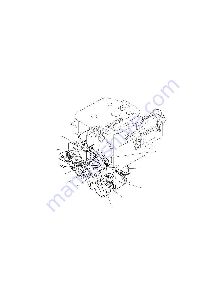
The forcible tape ejection mechanism consists of the eject rubber roller unit and the eject roller
unit driven under synchronizing with the cutter mechanism.
After tape printing and feeding, the cutter helical gear rotates counterclockwise when the cutter
mechanism starts to work (as described in Subsection 2.1.4) and the boss “A” on the gear
(engaged with the cam “G” of the eject roller unit) moves the eject roller unit around the shaft
“H”. After the cutter cuts the printed tape, the eject roller presses the tape against the eject
rubber roller. This motion of the eject roller unit is driven by the cam “G”.
After the cutter cuts the tape, the full cutter motor ASSY stops its rotation for a time. The eject
motor starts to rotate immediately after the cutter motor stops, which rotates the eject rubber
roller via the gear train to eject the nipped tape. Rotation of the eject rubber roller is stopped
after the given time and the full cutter motor ASSY starts to rotate again. The rotation of the
cutter helical gear opens the eject roller unit to the direction “J” by the force of the return spring.
Then the eject roller unit stops at the stopper “L” of the eject rubber roller unit.
Fig. 2.1-7 Forcible Tape Ejection Mechanism
Eject rubber roller unit
Eject roller
Return spring
“H”
“L”
“G”
“A”
Cutter helical gear
Full cutter motor ASSY
Eject roller unit
Summary of Contents for PT-9500PC - P-Touch 9500pc B/W Thermal Transfer Printer
Page 1: ...SERVICE MANUAL MODEL PT 9500PC ...
Page 2: ...SERVICE MANUAL MODEL PT 9500PC ...
Page 86: ...IV 10 3 The LED does not turn on 4 No printing is performed ...
Page 87: ...IV 11 5 The interface malfunction 6 The tape is not cut ...
Page 88: ...IV 12 7 The tape is not fed correctly ...
Page 89: ...IV 13 ...
Page 90: ...IV 14 8 Half cut failure ...
Page 91: ...IV 15 9 Forced tape eject failure ...
Page 92: ...IV 16 10 The failure of pressure contact release of the roller holder ...
Page 103: ......
Page 104: ......
Page 105: ......


