III-43
[ 12 ]
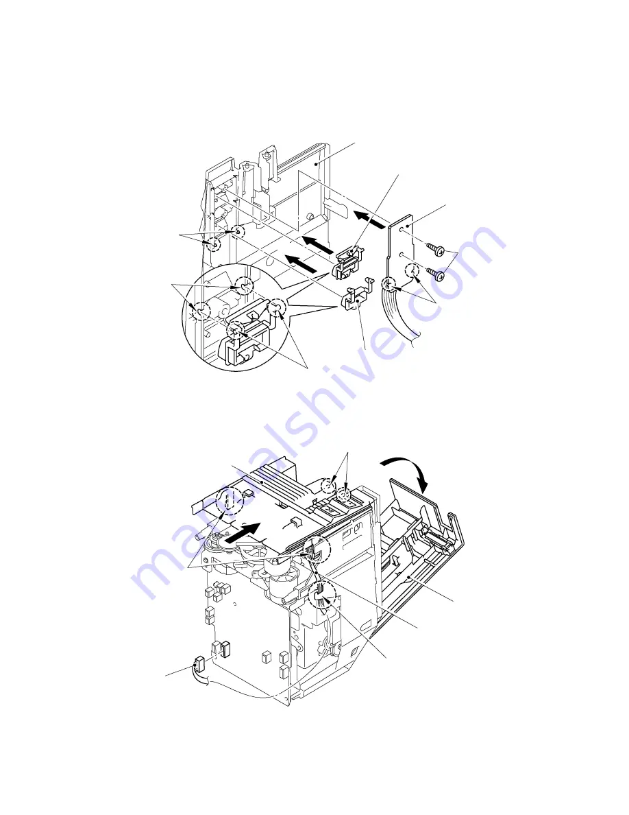
Reassembling of the Front Cover
(1)
Insert the bosses of the power supply switch button and the cut feed button into the guide
portions of the front cover.
(2)
Adjust the slit of the sub PCB ASSY to the bosses of the front cover and secure it with two
screws.
Fig. 3.1-73 Reassembling the Front Cover (1)
(3)
Open the cassette cover and insert the bosses of the front cover into the holes of the body
cover, then pushing the front cover to grip the hooks of both sides with the body cover.
(4)
Hook the harness of the sub PCB with the rib on the body cover and connect to the main
PCB.
Fig. 3.1-74 Reassembling the Front Cover (2)
Front cover
Power supply switch button
Sub PCB ASSY
Screws
Slit
Cut feed button
Bosses
Guide portion
Bosses
Pins
Cassette cover
Harness
Hook
Main PCB
Hooks
Front cover
1
2
Summary of Contents for PT-9500PC - P-Touch 9500pc B/W Thermal Transfer Printer
Page 1: ...SERVICE MANUAL MODEL PT 9500PC ...
Page 2: ...SERVICE MANUAL MODEL PT 9500PC ...
Page 86: ...IV 10 3 The LED does not turn on 4 No printing is performed ...
Page 87: ...IV 11 5 The interface malfunction 6 The tape is not cut ...
Page 88: ...IV 12 7 The tape is not fed correctly ...
Page 89: ...IV 13 ...
Page 90: ...IV 14 8 Half cut failure ...
Page 91: ...IV 15 9 Forced tape eject failure ...
Page 92: ...IV 16 10 The failure of pressure contact release of the roller holder ...
Page 103: ......
Page 104: ......
Page 105: ......


