4
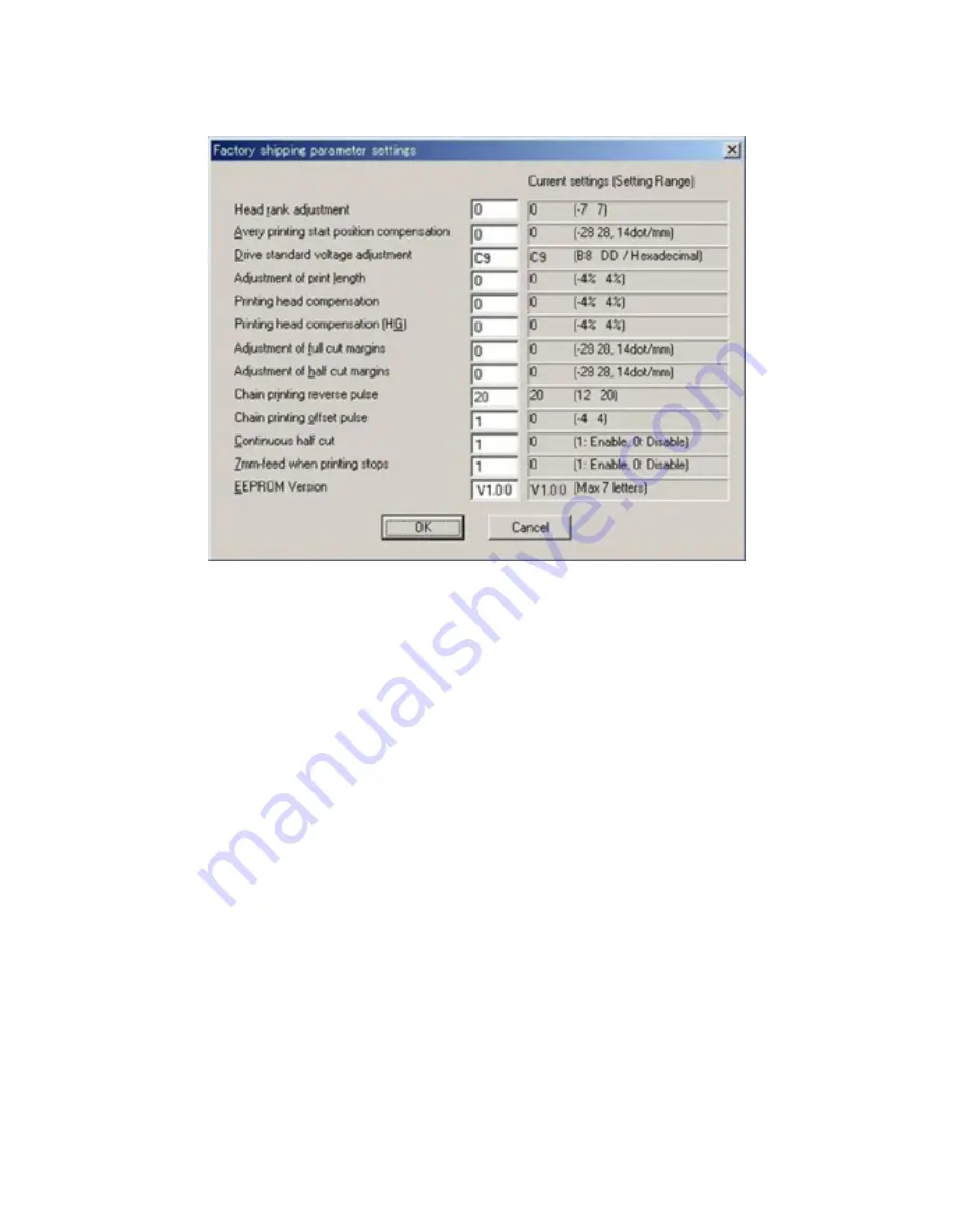
<Factory shipping parameter settings>
Fig. 4
Set the Factory shipping parameter settings screen before examination.
Note 1: Once this screen is set up, it is retained after the folder is closed.
Note 2: Connect the PT-9500PC to the serial port.
1)
Head rank adjustment
Input value: 0
Current value: 0
2)
Avery printing start position compensation
Input value: 0
Current value: 0
3)
Drive standard voltage adjustment
Input value: C9
Current value: C9
4)
Adjustment of print length
Input value: 0
Current value: 0
5)
Printing head compensation
Input value: 0
Current value: 0
6)
Printing head compensation (HG)
Input value: 0
Current value: 0
7)
Adjustment of full cut margins
Input value: 0
Current value: 0
8)
Adjustment of half cut margins
Input value: 0
Current value: 0
9)
Chain printing reverse pulse
Input value: 20
Current value: 20
10)
Chain printing offset pulse
Input value: 1
Current value: 1
11)
Continuous half cut
Input value: 1
Current value: 1
12)
7mm-feed when printing stops
Input value: 1
Current value: 1
13)
EEPROM Version
Input value: V1.00
Current value: V1.00
Note 1: Confirm the Input and current values of 1) ,2), 5), 6), 9), 10), 11), 12) are identical to the
above values respectively. In addition, use “PT95Reset.exe” software program to initialize
when different value comes on.
Note 2: Confirm the current value and input the same input value of 13) as the current value.
Note 3: The current value is the initial value of the EEPROM. Note that this value changes after the
shipping examination.
Summary of Contents for PT-9500PC - P-Touch 9500pc B/W Thermal Transfer Printer
Page 1: ...SERVICE MANUAL MODEL PT 9500PC ...
Page 2: ...SERVICE MANUAL MODEL PT 9500PC ...
Page 86: ...IV 10 3 The LED does not turn on 4 No printing is performed ...
Page 87: ...IV 11 5 The interface malfunction 6 The tape is not cut ...
Page 88: ...IV 12 7 The tape is not fed correctly ...
Page 89: ...IV 13 ...
Page 90: ...IV 14 8 Half cut failure ...
Page 91: ...IV 15 9 Forced tape eject failure ...
Page 92: ...IV 16 10 The failure of pressure contact release of the roller holder ...
Page 103: ......
Page 104: ......
Page 105: ......


