III-
39
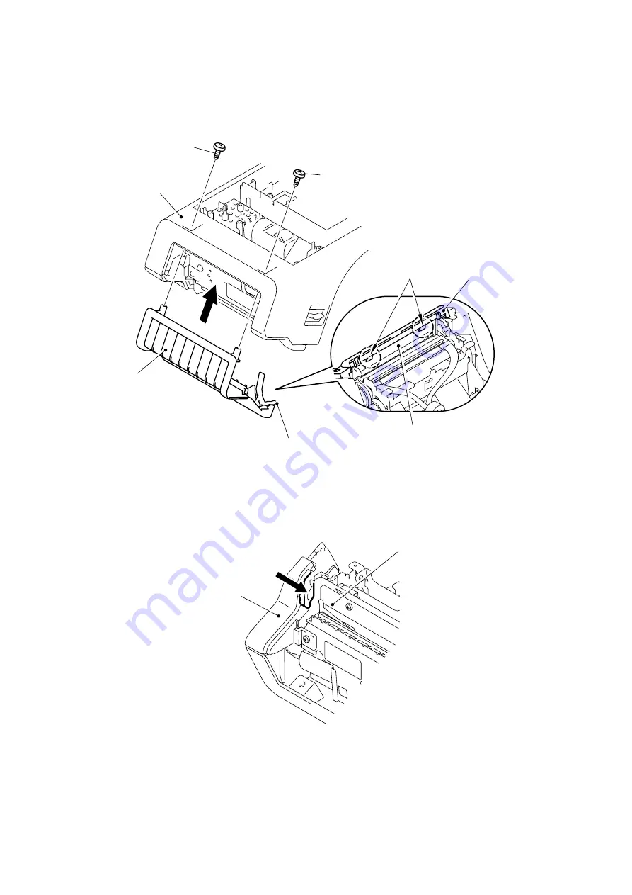
(4) Put the front cover onto the machine and lock the two hooks of the front cover onto the
cutter unit ASSY.
(5) Secure the front cover by tightening the two screws (taptite, bind B M3x8) from the bottom
of the machine.
Note: Put the cover sensor arm L into the gap between the cutter unit ASSY and front side
cover before assembling the front cover.
Fig. 3.2-22 Installing the
Front Side Cover, Panel Cover and Front Cover (4)
Screw
Screw
Under cover
Front cover
Hook
Cutter unit ASSY
Front cover
Cover sensor arm L
Cutter unit ASSY
Front side cover


