1. MECHANICAL DESCRIPTIONS
RH-981A
7
1-9. Cutter mechanism
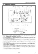
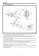
1. When cylinder 63 X 100 (1) operates, the motion is transmitted to the cylinder rod (2), link C (3), and link A (4),
which then activates the cutter lever assembly (5).
2. The cutter sensor partition plate (6) attached to link C (3), and the cutter sensor assembly (7) monitor the motion
of the cutter sensor assembly (5).
3. Engagement of the hammer (8) attached to the end of the cutter sensor assembly (5) and the cutter (9) attached
to the bed, cuts the material requiring button eyelets.
1-10. Looper mechanism
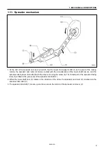
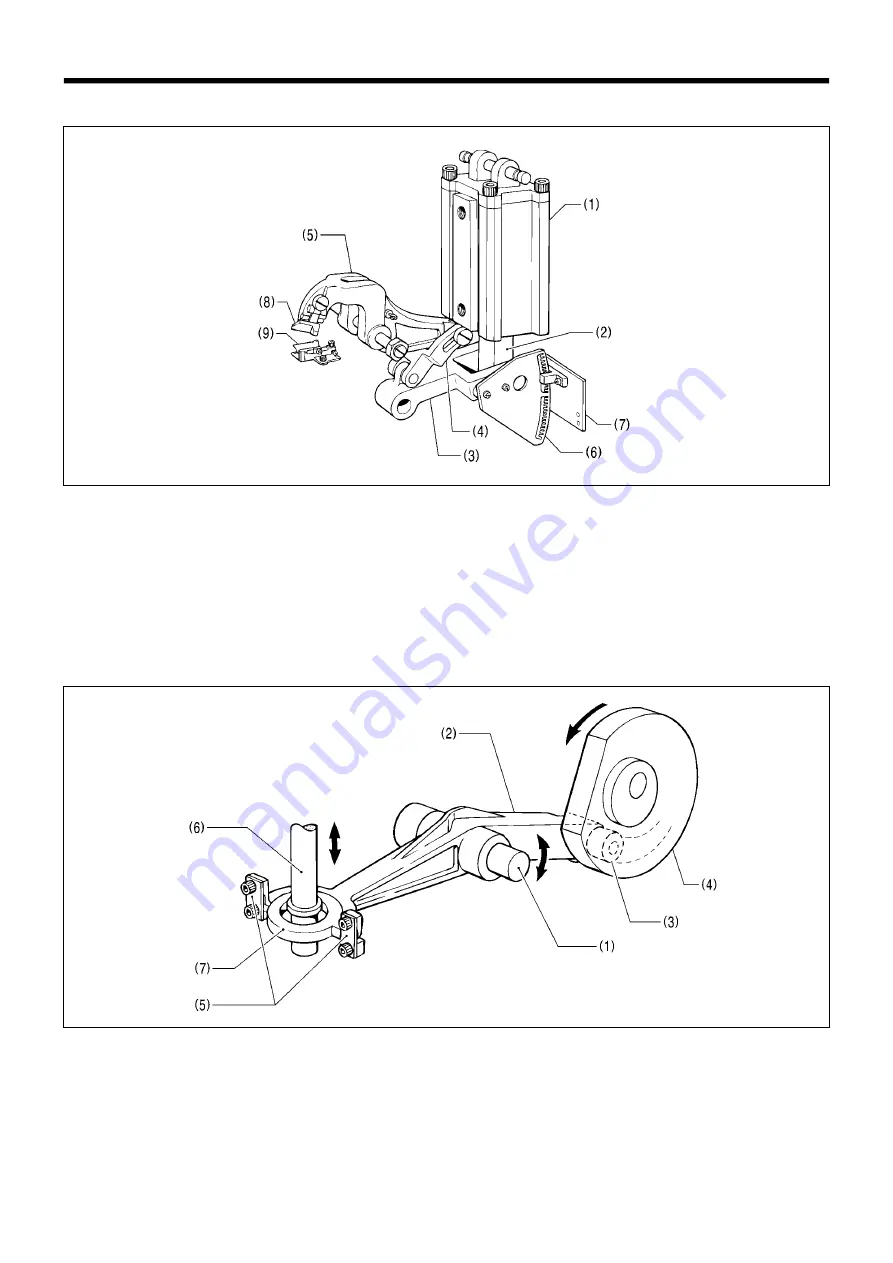
1. At the end of the looper link assembly (2) which has the looper link support shaft (1) as the pivot of the rocking
motion, the looper cam roller (3) is fitted in the groove in the lower shaft cam (4). The two looper link springs (5)
are attached to the other end.
2. The looper link springs (5) are secured by the looper driving plate (7) through which the looper driving shaft (6)
passes.
3. When the lower shaft cam (4) rotates in the direction of the arrow, the looper link assembly (2) is rocked via the
looper cam roller (3).
4. The looper driving shaft (6) moves up and down due to the motion of the looper link assembly (2).
3689Q
3690Q

