3. ASSEMBLY
RH-981A
28
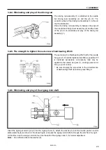
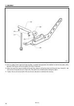
3-8-4. Eliminating end play of the driving rod
The driving rod assembly (1) is attached to the needle
bar driving lever assembly (2) and the pin (3). The
eccentric wheel of the driving rod assembly (1) is free in
the thrust direction.
Place the driving rod assembly (1) between the edge of
the needle bar driving lever assembly (2) and the head
of the pin (3) to eliminate end play of the driving rod
assembly (1).
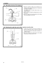
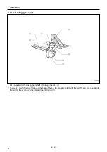
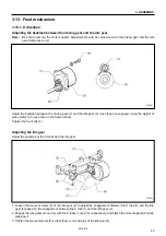
3-8-5. The strength to tighten the set screw of ball bearing 25/20
The set screw (3) of ball bearing 25/20 (2) for the needle
bar gear (1) should be tightened as little as possible. If it
is tightened excessively, unnecessary load may be
applied to the needle bar gear (1), causing pulse motor
R to go out of control.
* Be sure to apply the screw lock to the circumference
of ball bearing 25/20 (2) before press fitting it.
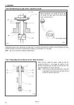
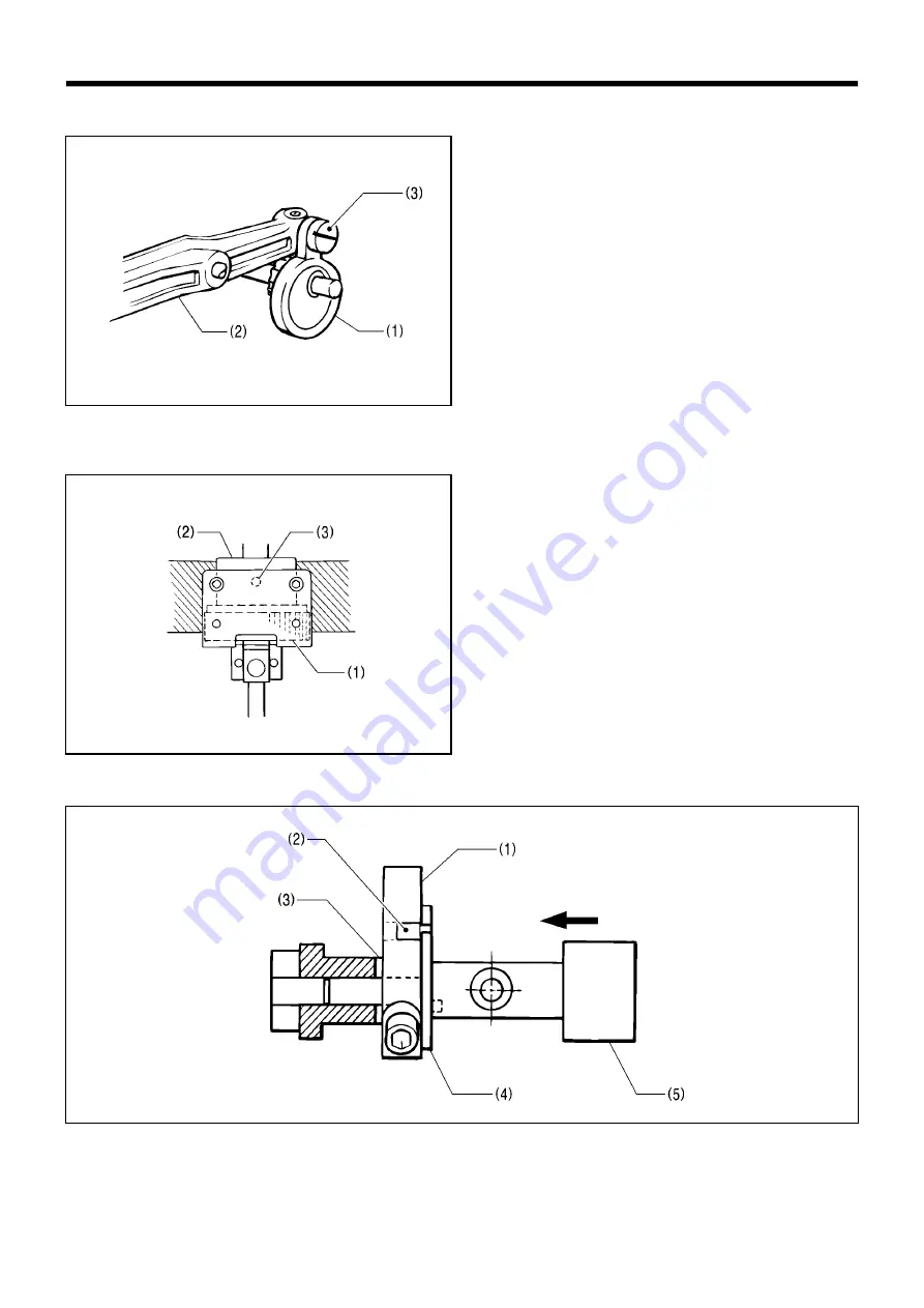
3-8-6. Eliminating end play of the zigzag rock shaft
Insert the zigzag eccentric pin (2) into the zigzag crank (1), attach the washer (3) and the needle position control
plate assembly (4) as shown in the above figure, and pass the zigzag rock shaft (5) through the arm from the right.
At this time, insert a wedge or similar tool into the split of the zigzag crank (1) for easier adjustment.
Note:
Do not fail to attach the washer (3).
3734Q
3735Q
3736Q


