5. POWER SUPPLY EQUIPMENT
RH-981A
78
5. POWER SUPPLY EQUIPMENT
DANGER
Wait at least 5 minutes after turning off the power switch and disconnecting the power cord from the wall
outlet before opening the face plate of the control box. Touching areas where high voltages are present
can result in severe injury.
Be sure to turn off the power and disconnect the plug before replacing and adjusting the parts associated with the
power supply equipment.
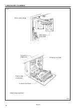
5-1. Components inside the control box
The following are brief explanations of components inside the control box. See control circuit block diagram at the
end of this manual for the details of the connections.
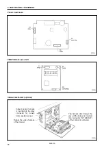
Control circuit board
The control circuit board is fixed to the rear panel of the control box.
This PCB serves to control machine operation.
Power supply circuit board
The power supply circuit board is fixed at the bottom of the control box.
Four fuses are mounted on this PCB. (Refer to “5-2. Fuse explanation”.)
PMD PCB for
θ
-axis shaft
The PMD PCB for
θ
-axis shaft is fixed to the board on the top of the control box.
This is used to run the
θ
-axis pulse motor.
DC fan motor (large)
Cools the heat sink on the PCB.
DC fan motor (small)
Discharges air in the control box. Clean the inlet filter monthly.
Conversion transformer (depending on power supply voltage specification)
Adjust the power voltage so that it is that required for the PCB.
* There are two types of transformers: a high voltage transformer is equipped with 240V, 380V, 400V, and 415V
specifications; a low voltage transformer is equipped with 100V and 110V specifications.
Transformer connections
1145S
Input side
1144S
Power supply
circuit board side
<415V, 400V, 380V, 240V>
<100V,110V>
Power supply
circuit board side
Input side


