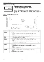
background image


S-7220C 

9. TROUBLESHOOTING

42

9. TROUBLESHOOTING 

  Please check the following points before calling for repairs or service. 

  If the following remedies do not fix the problem, turn off the power switch and consult a qualified technician or the place of 

purchase. 

        DANGER 


Wait at least 5 minutes after turning off the power switch and disconnecting the power cord from the wall outlet 
before opening the face plate of the control box. Touching areas where high voltages are present can result in 
severe injury. 


          CAUTION 


Turn off the power switch and disconnect the power cord before carrying out troubleshooting. 
The machine may operate if the treadle is depressed by mistake, which could result in injury. 


9-1. Sewing 

Items with a “*” in the “Page” column should only be checked by a qualified technician. 
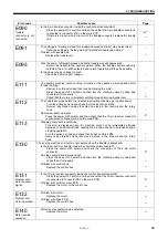
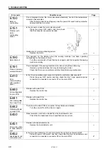
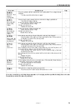
Problem Possible 

cause 

Page 

1  Upper thread is not tight. 

  Is the upper thread tension too weak, or is the lower thread tension 

too strong? 

Adjust the upper thread tension or lower thread tension. 


2  Lower thread is not tight. 

  Is the lower thread tension too weak, or is the upper thread tension 

too strong? 

Adjust the lower thread tension or upper thread tension. 


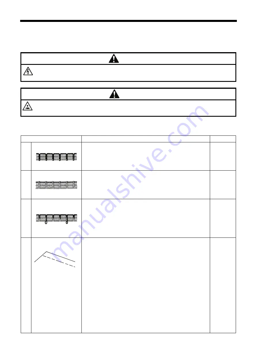
3  Loops appear in seam. 

  Is the thread path not smooth enough? 

Use a file with a fine grain or sandpaper to polish smooth the 
thread path. 

  Is the bobbin not turning smoothly? 

Pull out the lower thread to check that there is no slackness in 
the thread tension, or replace the bobbin or bobbin case. 


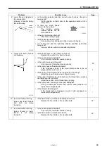
4 Skipped stitches occur 

while sewing 

  Is the needle tip bent? Is the needle tip blunt? 

If the needle tip is bent or broken, replace the needle. 

  Is the needle properly installed? 

If it is incorrect, install the needle correctly. 

  Is the machine properly threaded? 

If it is incorrect, thread the thread correctly. 

  Is the presser foot pressure too weak? 

Adjust the presser foot pressure. 

  Is the needle too thin? 

Replace the needle with a needle that is one rank thicker. 

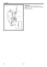
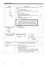
  Is the presser foot too high? 

Adjust the height of the presser foot. 

  Is the thread take-up spring too weak? 

Adjust the tension of the thread take-up spring. 

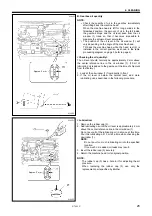
  Is the needle and rotary hook timing correct? 

Adjust the height of the needle bar.   
Adjust the clearance between the needle and the tip of the 
rotary hook. 


29 


40* 


35* 
36* 

0573M

0574M 

0977M 

0470M 


Summary of Contents for S-7220C

Page 1: ...20C INSTRUCTION MANUAL Please read this manual before using the machine Please keep this manual within easy reach for quick reference SINGLE NEEDLE DIRECT DRIVE NEEDLE FEED LOCK STITCHER WITH THREAD TRIMMER ...

Page 2: ...l sewing machines it is normal to carry out work while positioned directly in front of moving parts such as the needle and thread take up and consequently there is always a danger of injury that can be caused by these parts Follow the instructions from training personnel and instructors regarding safe and correct operation before operating the machine so that you will know how to use it correctly ...

Page 3: ...w this term indicate situations where failure to follow the instructions could result in death or serious injury CAUTION The instructions which follow this term indicate situations where failure to follow the instructions may result in minor or moderate injury Symbols This symbol indicates something that you should be careful of The picture inside the triangle indicates the nature of the caution t...

Page 4: ...al storm turn off the power and disconnect the power cord from the wall outlet Lightning may cause problems with correct operation Installation Machine installation should only be carried out by a qualified technician Contact your Brother dealer or a qualified electrician for any electrical work that may need to be done The sewing machine weighs approximately 46 kg 101 lb The installation should b...

Page 5: ...er injuries Use both hands to hold the machine head when tilting it back or returning it to its original position If only one hand is used the weight of the machine head may cause your hand to slip and your hand may get caught Be sure to wear protective goggles and gloves when handling the lubricating oil and grease so that they do not get into your eyes or onto your skin otherwise inflammation ca...

Page 6: ...t in severe injury Turn off the power before opening the cover 4 Be careful not to get your hands caught when returning the machine head to its original position after it has been tilted 3 5 Be careful to avoid injury from the moving thread take up 6 Be sure to connect the ground If the ground connection is not secure you run a high risk of receiving a serious electric shock and problems with corr...

Page 7: ...Oil pan Oil tank Transformer box 100 V 400 V system only Control box 0545D S 7220C v ...

Page 8: ...4 3 LOCK key 23 4 4 Resetting all settings to their defaults 24 5 SEWING 25 5 1 Adjusting the presser foot floating amount minute lifting amount 25 5 2 Sewing condensed stitches 26 6 CLEANING 27 6 1 Daily cleaning procedures 27 6 2 Applying grease When GrEASEUP appears 30 7 REPLACING THE FIXED KNIFE AND MOVABLE KNIFE 32 8 STANDARD ADJUSTMENTS 33 8 1 Adjusting the safety switch position 34 8 2 Adju...

Page 9: ...S 7220C ...

Page 10: ...ti min Max stitch length 4 5 mm 5 5 mm Lifting lever 6 mm Presser foot height Knee lifter 16 mm Feed dog height 1 0 mm 1 2 mm Needle DB 1 DP 5 11 18 19 22 Motor AC servo motor Control circuit Microprocessor 1 When sewing at speeds of 4 000 sti min or higher set the stitch length to 3 5 mm or less 2 When sewing at speeds of 3 000 sti min or higher set the stitch length to 4 5 mm or less Rotary hook...

Page 11: ... your hand to slip and your hand may get caught About the machine set up location Do not set up this sewing machine near other equipment such as televisions radios or cordless telephones otherwise such equipment may be affected by electronic interference from the sewing machine The sewing machine should be plugged directly into an AC wall outlet Operation problems may result if extension cords are...

Page 12: ...ld the weight and with stand the vibration of the sewing machine Drill holes as indicated in the illustration below Installation 1 Control box 1 Control box 2 Bolts 3 pcs 3 Nuts 3 pcs 4 Spring washers 3 pcs 5 Washers 3 pcs 2 Connecting rod 6 Connecting rod 7 Nut 4127M Control box mounting hole Head rest hole Cord hole Cotton stand hole 4126M ...

Page 13: ...bber cushions 2 pcs 2 Nails 4 pcs 5 Knee lifter complying bar 3 Knee lifter complying bar 6 Machine head 0549D 1 Hinges 2 pcs 2 Machine head 3 Head rest NOTE Tap the head rest 3 securely into the table hole If the head rest 3 is not pushed in as far as it will go the machine head will not be sufficiently stable when it is tilted back ...

Page 14: ...2 pcs Use the washers 2 and the screws 3 which are secured to the side plate 0551D 8 Sticker Remove 1 Sticker 9 Cotton stand 3636M 1 Cotton stand NOTE Securely tighten the nut 4 so that the two rubber cushions 2 and the washer 3 are securely clamped and so that the cotton stand 1 does not move ...

Page 15: ... 0553D Within 16 mm 4134M 4 Turn the screw 9 to adjust so that the amount of play in the knee lifter 8 is approximately 2 mm when the knee lifter plate 1 is gently pressed 5 Securely tighten the nut 7 6 Loosen the nut 10 7 Turn the screw 11 until the distance between the end of the screw 11 and the knee lifter 12 is approximately 3 mm 8 Turn the adjusting screw 11 to adjust so that the presser foo...

Page 16: ...ld always be lubricated and the oil supply replenished before it is used for the first time and also after long periods of non use 1 Hold the base of the nozzle of the accessory oil tank 1 and use scissors to cut about half way along the straight section A of the nozzle 2 Loosen and remove the nozzle and then remove the seal 2 3 Tighten the nozzle 4 Tilt back the machine head 5 Remove the rubber c...

Page 17: ... connect the power cord until all cords have been connected The machine may operate if the treadle is depressed by mistake which could result in injury When securing the cords do not bend the cords excessively or fasten them too hard with staples otherwise there is the danger that fire or electric shocks could occur Be sure to connect the ground If the ground connection is not secure you run a hig...

Page 18: ...ector 2 Binding the cords 1 Repeat cable tie NOTE Bind the cords in such a way that the connector does not get pulled out All cords that come out from the control box should be secured to the cord holder 2 using the repeat cable tie 1 otherwise vibration from the sewing machine may cause the cords to become disconnected which can cause problems with the operation of the control box 4140M Cords Pre...

Page 19: ... 4 pcs 3 Staples 7 pcs 4 Power cord 1 Attach an appropriate plug to the power cord 4 The green and yellow wire is the ground wire 2 Insert the power plug into a properly grounded electrical outlet NOTE Take care when tapping in the staples 3 to make sure that they do not pierce the cords Do not use extension cords otherwise machine operation problems may result Seen from underneath table Leg Contr...

Page 20: ...or 4 Power cord 5 Staples 5 pcs 1 Attach an appropriate plug to the power cord 4 The green and yellow wire is the ground wire 2 Insert the power plug into a properly grounded electrical outlet NOTE Take care when tapping in the staples 5 to make sure that they do not pierce the cords Do not use extension cords otherwise machine operation problems may result ...

Page 21: ...pcs 8 Cord clamps 2 pcs 9 Power cord 1 Attach an appropriate plug to the power cord 9 The green and yellow wire is the ground wire 2 Insert the power plug into a properly grounded electrical outlet NOTE Take care when tapping in the staples 7 to make sure that they do not pierce the cords Do not use extension cords otherwise machine operation problems may result 4150M Green and yellow wire ground ...

Page 22: ...essed the setting increases from 0 up to 99 When the key is pressed the setting decreases from 99 down to 0 3 Start backtack key When this key is pressed so that the indicator illuminates the number of start backtack stitches 0 99 in the A and B stitch number displays is sewn 4 End backtack key When this key is pressed so that the indicator illuminates the number of end backtack stitches 0 99 in t...

Page 23: ...e treadle is depressed to the maximum amount The sewing speed can also be adjusted while sewing is in progress When the key is pressed the sewing speed becomes faster When the key is pressed the sewing speed becomes slower 13 Thread trimming lock key When this key is pressed so that the indicator illuminates the sewing machine stops in the needle up position without thread trimming being carried o...

Page 24: ...ng until the set number of start backtack stitches has been sewn 4 End backtacking is carried out After it has finished the thread is trimmed automatically and the sewing machine stops in the needle up position NOTE If the treadle is depressed backward before sewing of the set number of start backtack stitches is complete end backtacking will not be carried out If the indicator of the thread trimm...

Page 25: ...ng carried out the sewing machine will stop at the point where the treadle returns to the neutral position If the treadle is depressed again operation will resume from the point where it was interrupted If the indicator of the thread trimming lock key is illuminated the sewing machine will stop in the needle up position without thread trimming being carried out Example 4177M 2159M Automatic sewing...

Page 26: ...ad trimming key to turn on the thread trimming function When the treadle is continuously depressed thread trimming is carried out after the fixed stitches have been sewn Automatic sewing When the AUTO key is pressed to turn on the automatic sewing function the fixed stitches are sewn simply by depressing the treadle once without needing to depress it continuously Start and end backtack sewing The ...

Page 27: ...2159M 2160M Automatic thread trimming Press the thread trimming key to turn on the thread trimming function Thread trimming is carried out automatically after the second set of F stitches has been sewn Automatic sewing When the AUTO key is pressed to turn on the automatic sewing function the fixed stitches in E and F are sewn respectively simply by depressing the treadle once without needing to de...

Page 28: ...3 Thread trimming is carried out 4180M Example 0556D 2160M Automatic sewing and automatic thread trimming These functions cannot be used Start and end backtack sewing The start backtack key and end backtack key can be pressed to turn on the backtack sewing function If changing the number of end backtack stitches indicated in C and D press the pleat presser sewing key to turn off the pleat presser ...

Page 29: ...itial setting value will be accepted when sewing starts 4182M 4183M Lower thread counter operation Sewing is possible until thread trimming is carried out Buzzer sounds for 5 seconds Press the RESET key 2 Reduces by 1 for every 10 stitches sewn Initial value 4184M 1 When sewing is carried out the value shown in the lower thread counter display is reduced by 1 for every 10 stitches sewn When the va...

Page 30: ...d so that the correction icon 22 illuminates correction sewing can be carried out If the sewing machine is stopped sewing will be carried out at slow speed 220 sti min while the actuator switch is being pressed NOTE If you press the actuator switch while sewing is in progress backtack stitches will be sewn Correction sewing cannot be carried out while the indicator of the pleat presser sewing key ...

Page 31: ...y the setting value will increase and the needle up stop position will become lower If you press the key the setting value will decrease and the needle up stop position will become higher The setting range is from 5 to 10 A setting value of 10 corresponds to an angle of rotation of approximately 10 for the upper shaft 4 The setting values will be memorized 4192M 5 Normal sewing machine operation w...

Page 32: ...s state the following three key operations are disabled so that the setting values cannot be changed accidentally FUNC key 3 This key is used to make settings for various functions ENTER key 4 This key is used to accept function settings MAX key 5 This key is used to change the maximum sewing speed Refer to the Service Manual for details on using these keys 4194M ...

Page 33: ... press the power ON switch init ALL will appear in orange in the main display 1 1 2 Press for 2 seconds or more Once initialization is complete the main display will return to green 4192M 3 Initialization mode will be exited and normal sewing machine operation will then be possible 4193M 4195M If the X keys 2 are pressed at this time you can select the items to be initialized as shown below For de...

Page 34: ...justing the presser foot floating amount minute lifting amount When sewing stretch materials and materials with long pile you can make minute adjustments to the floating amount for the presser foot 1 in accordance with the material 1 Turn the sewing machine pulley by hand to move the feed dog 2 below the needle plate 3 2 Use the lifting lever to lower the presser foot 1 3 Loosen the nut 4 4 Use a ...

Page 35: ...the machine head 4 Loosen the nut 5 and then turn the bolt 6 until its head is touching the solenoid lever 7 5 Tighten the nut 5 to secure the bolt 6 6 Return the machine head to its normal position Sewing 1 Return the stitch length dial 4 to the stitch length for normal sewing 2 Push down the dial lock lever 3 to engage the lock 3 Start sewing 4 At the position where you would like to start sewin...

Page 36: ...f the table moves it may crush your feet or cause other injuries Use both hands to hold the machine head when tilting it back or returning it to its original position If only one hand is used the weight of the machine head may cause your hand to slip and your hand may get caught 6 1 Daily cleaning procedures The followinig cleaning operations should be carried out each day in order to maintain the...

Page 37: ... in the oil window 1 70 ml of lubricating oil is added to the gearbox at the time of shipment from the factory 1 Look at the oil window 1 from directly in front 2 If the oil level is below the normal level add more lubricating oil as described in the following procedure Approx 2 mm 2186M 0564D Approx 2 mm 2188M 0565D Lubrication 1 Remove the rubber cap 3 2 Add lubricating oil until the oil level i...

Page 38: ...S 7220C 6 CLEANING 29 2 Checking 0559D 1 Replace the needle if it is bent or if the tip is broken 2 Check that the upper threads have been threaded correctly 3 Carry out a test sewing ...

Page 39: ...se when the GrEASEUP notification flashes the notification will continue to flash each time the power is turned on until you reset the notification by carrying out the procedure on the following page If you continue to use the sewing machine after the GrEASEUP notification appears without applying grease or without carrying out the reset procedure E100 will appear after a certain period of time an...

Page 40: ...cloth to wipe away any excess grease from around the screws 7 Carry out the reset procedure given below 0562D Resetting the grease consumption amount After the grease has been applied carry out the following procedure to reset the grease consumption amount 1 While pressing the key 3 and the key 4 at the right end simultaneously press the power ON switch 2 GuCt xxx will appear in the main display 1...

Page 41: ...se only genuine Brother parts Brother will not be held responsible for any accidents or problems resulting from the use of non genuine parts Fixed knife 0569D 1 Tilt back the machine head 2 Remove the screw 1 and then remove the hook stopper 2 3 Remove the screw 3 and then remove the fixed knife 4 NOTE Carry out the above steps in reverse to install the fixed knife 4 Sharpening the fixed knife If ...

Page 42: ... If the table moves it may crush your feet or cause other injuries Use both hands to hold the machine head when tilting it back or returning it to its original position If only one hand is used the weight of the machine head may cause your hand to slip and your hand may get caught Turn off the power switch and disconnect the power cord from the wall outlet at the following times otherwise the mach...

Page 43: ...tween the machine head and the table hole is 1 5 mm If the clearance is 3 5 mm or more install the safety switch 1 so that the washer 2 is on the machine head side as shown in Figure B If the position cannot be satisfactorily adjusted in this way add more washers of the same thickness Safety switch operation 3690M Sewing machine 3692M 3 5 mm or more If the spring stroke is to small the safety swit...

Page 44: ...edle plate 4 and the feed dog 5 2 Turn the machine pulley to set the needle bar 1 to its lowest position 3 Remove the rubber cap 6 from the face plate 4 Loosen the screw 7 5 Move the needle bar 1 up or down to adjust so that the distance from needle plate mounting surface A to the bottom edge of the needle bar 1 is the same as the height of surface B on the 1 side of the accessory timing gauge 2 6...

Page 45: ...rews 9 which are securing the rotary hook 8 4 Turn the machine pulley to raise the needle bar 1 from its lowest position until the distance from needle plate mounting surface A to the bottom edge of the needle bar 1 is the same as the height of surface C on the 2 side of the accessory timing gauge 2 5 Loosen the remaining set screw 9 and align the rotary hook tip 3 with the center of the needle 4 ...

Page 46: ...er Becomes higher Needle plate 3764M 0576D 4 3 1 0 mm 405 1 2 mm 1 Turn the pulley until the feed dog 1 rises to the highest position 2 Tilt back the machine head 3 Loosen the screw 2 4 Turn the feed lifting rock bracket stud 3 within a range of 90 from the reference line 4 to adjust the vertical height of the feed bar 5 Fig A 5 Tighten the screw 2 If you are worried about the angle of the feed do...

Page 47: ...a range of 90 with respect to the standard position Fig C In order to prevent puckering lower the front of the feed dog 1 In order to prevent the material from slipping raise the front of the feed dog 1 5 Securely tighten the set screws 4 If you would like to tilt the feed dog 1 further turn the feed lifting rock bracket stud 5 while carrying out the above adjustment Fig D Refer to 8 4 Adjusting t...

Page 48: ...e vertical cam 3 4 3 There is a gap of approximately 2 mm between the tip of the needle and the top of the needle plate 2 405 There is a gap of approximately 4 mm between the tip of the needle and the top of the needle plate 2 1 Set the stitch length dial to the maximum setting 2 Tilt back the machine head 3 Loosen the two set screws 5 and then turn the vertical cam 3 sligtly to adjust the timing ...

Page 49: ... Adjusting the presser foot height The standard height of the presser foot 1 is 6 mm when the presser foot 1 is raised by means of the lifting lever 2 Needle 0580D 1 Loosen the nut 3 of the adjustment screw 4 and then turn the adjustment screw 4 so that there is no pressure applied to the presser foot 2 Raise the lifting lever 2 The presser foot 1 will also rise 3 Remove the oil cap 5 4 Loosen the...

Page 50: ...ng speed for 8 seconds Any type of paper can be used as the lubrication amount check sheet 1 5 Check the amount of oil which has spattered onto the sheet If adjustment is necessary carry out the following operations in Adjusting the lubrication amount NOTE If the lubrication amount does not match the correct amount shown in the illustration at left if the amount of spattered oil is too much or non...

Page 51: ...ower thread tension too weak or is the upper thread tension too strong Adjust the lower thread tension or upper thread tension 3 Loops appear in seam Is the thread path not smooth enough Use a file with a fine grain or sandpaper to polish smooth the thread path Is the bobbin not turning smoothly Pull out the lower thread to check that there is no slackness in the thread tension or replace the bobb...

Page 52: ...the needle up stop position 32 21 22 6 Uneven seam Is the presser foot pressure too weak Adjust the presser foot pressure Is the feed dog too low Adjust the feed dog height Is the bobbin scratched If the bobbin is damaged smooth it with an oiled grindstone or replace it 7 Large degree of puckering excess tension Is the upper thread tension too strong Make the upper thread tension as weak as possib...

Page 53: ...correct thread the thread correctly Is the rotary hook sufficiently lubricated If the oil gauge is down to the lower reference line in the oil gauge window add more oil Is the upper or lower thread tension too weak or too strong Adjust the upper thread or lower thread tension Is the upper thread may be loose because the thread take up spring operating range is too small Adjust the position of the ...

Page 54: ... taken to account for such needles to comply with product liability regulations 35 36 39 13 Oil gauge 1 is not visible in oil gauge window Is the oil tank empty Fill the oil tank with oil 7 14 Machine does not operate when power is turned on and treadle is pressed Is the power supply connector disconnected from the control box Insert the connector securely 11 12 15 Machine does not operate at high...

Page 55: ... disconnected from the control box Insert the connector securely Is the operation panel connector inside the control box disconnected Insert the connector securely 11 12 9 18 GrEASEUP flashes in the panel display when the power switch is turned on This display is to notify you that it is time to apply grease Apply grease 30 4264M 4263M ...

Page 56: ...ge Page E050 The machine head was detected as being tilted back when the treadle was depressed Press the power OFF switch and then return the machine head to the upright position If tilting back the machine head to carry out any tasks press the power OFF switch first E051 The machine head was detected as being tilted back during sewing Turn the power off and then back on again E055 Was the power O...

Page 57: ...check that it does not turn stiffly Remove any thread scraps that may be stuck in the area around the rotary hook Abnormal needle up signal Press the power OFF switch and then check that the 10 pin resolver connector is connected to connector P6 on the main PCB 9 E113 Stopping could not be confirmed This error is displayed when the machine could not be immediately stopped because of an abnormal lo...

Page 58: ...t there are no problems with the thread trimming mechanism E410 Error communicating with operation panel Is the 12 pin operation panel connector inside the control box disconnected Press the power OFF switch and then check that the 12 pin operation panel connector is connected to connector P7 on the main PCB 9 E440 Error writing data to main PCB Problem with main PCB Replace the control box E441 E...

Page 59: ...place the control box E710 Motor overcurrent Is the electrical equipment connector inside the control box disconnected Press the power OFF switch and then check that the drive PCB connector is connected to connector P4 on the main PCB This is displayed if the machine pulley moves stiffly when it is turned by hand or if the sewing machine locks up and an abnormal current is flowing Press the power ...

Page 60: ...S 7220C 10 7 SEGMENT DISPLAY 51 10 7 SEGMENT DISPLAY 4268M ...

Page 61: ...S 7220C MEMO ...

Page 62: ...at the contents of this manual may differ slightly from the actual product purchased as a result of product improvements 2013 Brother Industries Ltd All Rights Reserved S 7220C SB4251 001 E 2013 04 D 1 This is the original instructions ...

Reviews: