


-12-
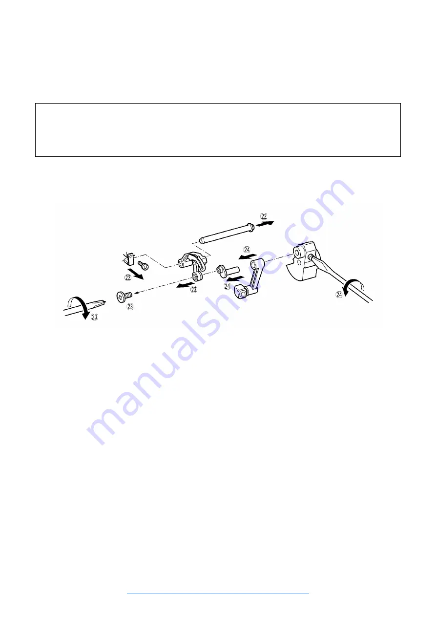
22. Remove the screw holding the thread take-up lever shaft fastening plate, then remove the thread take-up
lever shaft.
23. Remove the left thread take-up lever screw, then remove the thread take-up lever.
24. Loosen the thread take-up crank set screw, then remove the needle bar crank and the needle bar crank rod.
Disassembly Point
23. Remove the left thread take-up lever screw by holding the balance wheel by hand so that the upper shaft
does not turn and turning the screwdriver to the right.
24. Loosen the thread take-up crank set screw by holding the balance wheel by hand so that the upper shaft
does not turn.
www.promelectroavtomat.ru
Summary of Contents for XL-6040
Page 1: ... 6 2001 www promelectroavtomat ru ...
Page 3: ... 1 I 1 MECHANICAL CHART 2 2 POWER TRANSMISSION CHART 3 www promelectroavtomat ru ...
Page 4: ... 2 1 MECHANICAL CHART www promelectroavtomat ru ...
Page 29: ... 27 2 LEAD WIRES ARRANGEMENT www promelectroavtomat ru ...
Page 61: ...XL 6060 Series XL 6050 Series XL 6040 Series H1040194 www promelectroavtomat ru ...


