


-15-
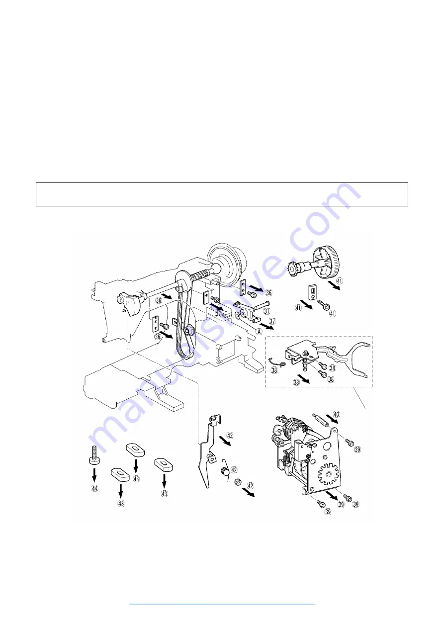
36. Remove the total of two screws securing the left and right metal pressers and remove the upper shaft
assembly.
37. Remove the screw securing the fastening plate, then remove the feed regulator and feed regulator shaft.
38. (XL-6060, XL-6050 series only)
Remove the two screws securing the BH stopper assembly, then remove the BH stopper assembly and
spring.
39. Remove the three screws securing the selection unit, then remove the selection unit.
40. Remove the M4 hex screw.
41. Remove the screw securing the presser plate, then remove the selection dial assembly.
42. Remove the CS lock ring, then remove the torsion spring and the thread slack plate C.
43. Remove the three bottom leg rubber pads.
44. Remove the leg adjustment screws.
Disassembly Point
37. When removing the feed regulator, be careful not to lose the plastic washer (A).
These parts are not
used for XL-6040
series
www.promelectroavtomat.ru
Summary of Contents for XL-6040
Page 1: ... 6 2001 www promelectroavtomat ru ...
Page 3: ... 1 I 1 MECHANICAL CHART 2 2 POWER TRANSMISSION CHART 3 www promelectroavtomat ru ...
Page 4: ... 2 1 MECHANICAL CHART www promelectroavtomat ru ...
Page 29: ... 27 2 LEAD WIRES ARRANGEMENT www promelectroavtomat ru ...
Page 61: ...XL 6060 Series XL 6050 Series XL 6040 Series H1040194 www promelectroavtomat ru ...


