


-22-
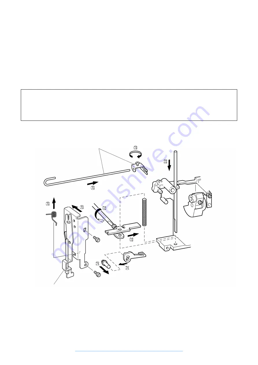
71. Install the presser lifter shaft on the arm and install the presser lifter.
72. Pass the presser bar over the presser spring and presser bar clamp.
Temporarily tighten the presser bar screw. (See Adjustment Procedure 13.)
73. (XL-6060, XL-6050 series)
Install the torsion spring on the BH lever installation plate, install the BH lever installation plate with the two
screws, then install the BH change shaft, and fasten with the screw.
(XL-6040 series)
Install the torsion spring on the BH lever installation plate, install the BH lever installation plate with the two
screws.
Assembly Points
72. Pass the presser bar through the presser spring and presser bar clamp while compressing the presser
spring. Be careful that the presser spring does not pop out. After installing the presser bar, move the
presser lifter up and down and check it moves freely.
73. Set the BH lever installation plate in the presser bar clamp groove.
These parts are not used
for XL-6040 series
BH lever is not used for
XL-6040 series
www.promelectroavtomat.ru
Summary of Contents for XL-6040
Page 1: ... 6 2001 www promelectroavtomat ru ...
Page 3: ... 1 I 1 MECHANICAL CHART 2 2 POWER TRANSMISSION CHART 3 www promelectroavtomat ru ...
Page 4: ... 2 1 MECHANICAL CHART www promelectroavtomat ru ...
Page 29: ... 27 2 LEAD WIRES ARRANGEMENT www promelectroavtomat ru ...
Page 61: ...XL 6060 Series XL 6050 Series XL 6040 Series H1040194 www promelectroavtomat ru ...


