-23-
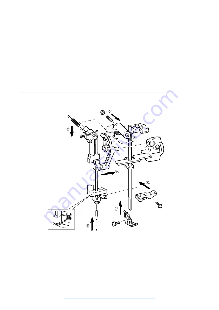
74. Insert needle bar block assembly shaft into the arm hole, insert the needle bar holder shaft into the needle
bar crank rod, then install the needle bar block assembly. Screw in the setscrew from the rear of the arm,
position the needle bar block assembly forward and rear and tighten the lock nut. (See Adjustment
Procedure 7.)
75. Install the needle bar supporter stud holder assembly with the screw.
76. Hang the needle bar block assembly tension spring on the arm and needle bar block assembly.
77. Install the presser clamp on the presser bar with the screw and install the presser foot.
78. Install the needle and tighten the needle set screw.
Assembly Points
74. If the upper shaft is set to the phase with the needle bar at its lowest point, it is easier to insert the needle
bar holder shaft into the needle bar crank rod.
74. Hang the BH lever installation plate torsion spring.
www.promelectroavtomat.ru
Summary of Contents for XL-6040
Page 1: ... 6 2001 www promelectroavtomat ru ...
Page 3: ... 1 I 1 MECHANICAL CHART 2 2 POWER TRANSMISSION CHART 3 www promelectroavtomat ru ...
Page 4: ... 2 1 MECHANICAL CHART www promelectroavtomat ru ...
Page 29: ... 27 2 LEAD WIRES ARRANGEMENT www promelectroavtomat ru ...
Page 61: ...XL 6060 Series XL 6050 Series XL 6040 Series H1040194 www promelectroavtomat ru ...