background image

KESMAC

Transportable Forklifts

Operators Manual

Summary of Contents for 4500

Page 1: ...KESMAC Transportable Forklifts Operators Manual ...

Page 2: ...avel with load raised higher than necessary e For better vision with bulky loads travel in reverse f Lift and lower loads with the mast vertical or tilted slightly back 15 As a further safety precaution it is recommended that a fire extinguisher be carried in a convenient location on the machine at all times 16 When checking engine coolant remove the radiator cap slowly to relieve pressure and alw...

Page 3: ......

Page 4: ...y Chart Transporting Loads 22 Maintenance 26 Daily Inspection 26 Air Cleaner Service 28 Hydraulic System 30 Oil Change 31 Hydraulic Pump Drive Belt Adjustment 32 Revised Sept 06 Wheels and Tires 33 Electrical System 34 Electrical Schematic 35 Automotive Controller 36 Electrical Schematic 37 Blink Codes Translation 38 Fault Codes 39 Maintenance Schedule 40 Lubrication 42 Transportation 45 IMPORTANT...

Page 5: ...e Do not operate the machine if any safety device or warning decal is damaged or missing IMPORTANT To ensure the long term safe and satisfactory performance of the machine the maintenance and service procedures outlined in this manual must be followed It is in the customers interest that the machine is serviced and maintained as recommended and not abused in any way as the warranty may be voided W...

Page 6: ...anual The operator should at all times be aware of any potential safety hazards and take corrective action immediately if a dangerous situation should arise IF YOU DO NOT UNDERSTAND ASK BE A QUALIFIED OPERATOR SERVICE PERSON BY Reading and following the instructions in this manual and those on the safety decals Receiving training on the correct and safe oper ration of the machine Asking your super...

Page 7: ...ance practices to ensure your own safety and that of others Warning and safety decals are prominently displayed and strategically placed on the machine Before operating the machine check that all warning and safety decals are in place are not damaged and are easily readable See the following pages for the locations of the safety decals It is important that you familiarize yourself with the decals ...

Page 8: ...ations Replacement tires must meet the Kesmac specifications Do not exceed the operating pressure shown on the tire sidewall The wheel retaining nuts must be checked regularly for tightness Operating the machine with loose wheel nuts will result in damage to and require the replacement of wheel components WARNING When removing wheel assemblies exercise extreme caution Use only a hoist with adequat...

Page 9: ......

Page 10: ......

Page 11: ......

Page 12: ...11 3 10 4 8 1 5 7 6 2 9 REAR WHEEL BATTERY ENGINE COMPARTMENT 9 ...

Page 13: ...or 33 x 12 50 15 NHS 8 Ply Engine Kubota V 1505 Diesel 4 Cyl Kubota V 1505 T Turbo Diesel 4 Cyl Kubota V 1505 T Turbo Diesel 4 Cyl Output 37 5 HP 3000 RPM 46 5 HP 3000 RPM 46 5 HP 3000 RPM Gross Intermittent Gross Intermittent Gross Intermittent Max Travel Speed 8 mph 13 kph 8 mph 13 kph 8 mph 13 kph Drive 3 Wheel Hydrostatic 3 Wheel Hydrostatic 3 Wheel Hydrostatic Fork Carriage I T A Class 11 I T...

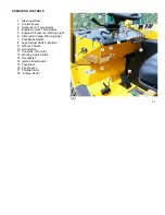
Page 14: ... 5 Engine Oil Pressure Warning Light 6 Alternator Charge Warning Light 7 Park Brake Switch 8 Legs Retract Switch Option 9 Diff Lock Switch 10 Horn Button 11 Pre Heat ON Light 12 Working Lights Switch 13 Hour Meter 14 Ignition Start Switch 15 Fuse Block 16 F N R Lever 17 Throttle Pedal 18 Inching Pedal Fig 1 11 ...

Page 15: ... the engine is running Engine Pre Heat is required when the ambient temperature is below 50 deg F 10 deg C Hold the key in the Pre Heat position for 5 to 10 seconds Before starting the engine F N R LEVER Fig 3 The F N R Lever must be in NEUTRAL before starting the engine IMPORTANT If the engine is started with the F N R Lever in forward or reverse the machine will not move until the lever is put i...

Page 16: ...ing or unloading the Forklift on or off a truck or trailer LEVER A Forward Forks DOWN Rearward Forks UP LEVER B Forward Tilt FORWARD Rearward Tilt BACK LEVER C Forward Side Shift LEFT Rearward Side Shift RIGHT LEVER D Forward Carriage OUT Rearward Carriage IN Fig 4 LEVER E Forward Stabilizer DOWN Rearward Stabilizer UP 13 ...

Page 17: ...e the forks when the legs are re tracted Failure to follow these instructions may result in the machine tipping resulting in serious injury or death 14 To retract extend the legs Fig 5 Position the Shift Lever in NEUTRAL and start the engine The mast must be fully forward Put the Park Brake Switch in the OFF position Press and hold down the Extend Retract Switch and at the same time pull the Contr...

Page 18: ... the Diff Lock Select FORWARD Push and hold down the Diff Lock switch in the ON position Slowly press the Throttle Pedal to increase the travel speed Release the Diff lock switch IMPORTANT The Diff Lock must be used for straight line travel only The Diff Lock must not be engaged if the travel speed exceeds 4 mph 6 Kph or if one of the wheels is spinning Fig 6 15 ...

Page 19: ...ows for more precise control when positioning picking up or placing a load Pressing the Inching Pedal completely down will bring the forklift to a stop while high engine speed can be main tained to allow the full speed operation of the hydraulic functions without shifting to NEUTRAL WARNING The Inching Pedal does not function as a Fig 7 park brake It is recommended that the park brake is applied w...

Page 20: ...removing the radiator cap in order to check the coolant level Rectify any leaks and top up the coolant before operating the machine HYDRAULIC OIL Temperature Normal operating temperature is 160 deg F 71 deg C If the temperature approaches 200 deg C 93 deg C Let the engine idle for a short time If the temperature remains high shut down the machine immediately Check for hydraulic oil leaks Allow the...

Page 21: ...ENGINE OIL PRESSURE If the Engine Oil pressure Warning Lamp is ON when the engine is running switch the engine OFF immediately Locate and rectify the problem before operating the machine ALTERNATOR LAMP The Alternator Lamp will be ON when the Ignition Key is in the ON position but the engine not running If the Warning Lamp comes ON when the engine is running switch the engine OFF Locate and rectif...

Page 22: ... connections Excessive wear or damage to the tires Damage to the wheel rims and missing or loose lug nuts All fluid levels Top up as necessary That the operating controls are not damaged are correctly adjusted and working properly The operator s seat and seat belt are properly adjusted and secured Check around and under the machine for water or oil leaks IMPORTANT Do not operate the machine if any...

Page 23: ...IMPORTANT For the correct starting procedure maintenance service operation and specifications for the Kubota Diesel Engine used on the Kesmac Forklift refer to the Kubota Operator s Manual that is supplied with the machine 20 When traveling Avoid inclines and rough un even ground If it is un avoidable proceed slowly with extreme caution DO NOT Turn the machine when on an incline Drive across an in...

Page 24: ...en operating on an incline DANGER In the event that the machine tips over hold the steering wheel firmly brace your feet and lean in the opposite direction to the tip over Failure to observe this warning will result in serious injury or death Without a load Keep the forks as close to the ground as possible and the mast carriage fully extended Always drive with SAFETY in mind Do not take chances We...

Page 25: ... serious injury or death 22 The shape of the load can affect the maneuverability of the machine Operate with caution when lifting long or odd shaped loads If the load exceeds the lifting capacity it must be broken down into two loads To rate the lifting capacity of Forklift Machines a standardized load is used based on a 48 inch cube the center of which is the center of gravity This is referred to...

Page 26: ...RNING Do not use the Side Shift when traveling with a load and the forks raised To do so could cause the machine to tip over resulting in serious injury or death If there is any indication of loss of stability when lifting a load STOP IMMEDIATELY and lower the load Identify and correct the problem before continuing operating the machine WARNING Before leaving the operator s seat Lower the forks to...

Page 27: ...andle B Fully retract the Mast Carriage keeping the load 6 to 8 inches from the ground A wide load will be positioned above the Legs Raise the Stabilizers Handle E Transport the load to its required location 24 If driving conditions demand added traction activate the Diff Lock to help maintain a travel speed of 3 to 5 mph Refer to Figure 8 IMPORTANT Do not engage the Diff Lock If the machine is tr...

Page 28: ...erse away from the load IMPORTANT Keep the forks as close as possible to but clear of the ground and avoid any obstacles Also For better visibility and increased stability when operating without a load maneuver with the Carriage fully extended Fig 14 CAUTION The rear location of the Steer Wheel causes the back of the machine to swing out when turning sharply always turn slowly Exercise caution for...

Page 29: ...he mast Remove dirt or debris from around the foot controls On retractable models clean around the lower sliders Do not direct the pressure wash water jet directly into any electrical components ENGINE COMPARTMENT Fig 15 To check the Engine Oil Level Engine Coolant Level Air Cleaner Hydraulic Oil Level To access the engine compartment Release the Hood Closing Catches A Lift the Hood Handle B and a...

Page 30: ...ed service procedures DIESEL FUEL TANK Fig 16 The fuel tank is located to the right of the operator s seat Tank capacity is 7 US gallons 28 4 liters The fuel level indicator is in the filler cap IMPORTANT Clean around the Filler Cap before removing it Do not allow dirt or water to enter the tank Use well filtered fuel Do not allow the tank to run dry Fig 16 27 ...

Page 31: ...ading Filter service based on indicator readings gives a longer filter life and better engine protection This results in lower maintenance service costs reduces possible problems such as contamination and filter damage When the Servi Signal unit shows a Red Flag in the full view window this is the indication that the filter requires attention IMPORTANT When the service procedure is complete the Re...

Page 32: ...move it carefully to prevent dust being dislodged Carefully pull the filter off the outlet tube and out of the housing Avoid knocking the filter against the safety element and the housing With a clean cloth wipe the sealing surface on the outlet tube Dust on this will result in poor sealing and air leakage All contaminants must be removed before installing the new filter Visually inspect the disca...

Page 33: ...ary IMPORTANT Check that all clamps bolts and connections in the air intake system are tight and free from leaks Check the hoses and pipes for holes and repair or replace as necessary 30 HYDRAULIC SYSTEM LOW RANGE STANDARD RANGE HIGH RANGE 20 deg C to 25 deg C 10 deg C to 25 deg C 20 deg C to 45 deg C 4 deg F to 77 deg F 4 deg F to 95 deg F 32 deg F to 113 deg F Castrol Hyspin AWH 32 AWH 46 AWH 68...

Page 34: ...t be removed from the system by a qualified hydraulic service center as soon as possible OIL LEVEL Check the oil level in the sight gauge It should be at the half full mark with all cylinders retracted legs extended when applicable and the oil warm Fig 19 START UP procedure after oil change The oil in the lines cylinders valves and pump will be cleaner than the new oil To minimize contamination do...

Page 35: ...flection of the belt at point C midway between the engine and pump sheaves Tighten the lock nut A IMPORTANT On a new machine check the Drive belt tension after the first 20 hours of operation Then after every 100 hours of operation Fit a new Drive Belt every 750 hours of operation or every 12 months 32 Fig 20 DRIVE BELT REPLACEMENT Fig 20 To remove the Drive belt Loosen the lock nut A sufficient t...

Page 36: ... tire pressure Std Tire Opt Tire Load Pounds 3000 3000 3000 35 psi 25 psi 3500 3500 3500 40 30 4000 4000 4000 50 35 4500 4500 55 40 5000 5500 60 45 Rear tire All loads 35 psi 30 psi IMPORTANT Check regularly Lug nuts Tighten to 100 lb ft 135 Nm Do not over tighten the lug nuts That the tires are not damaged have no bulges and are not excessively worn That the wheel rims are not cracked or damaged ...

Page 37: ...der 2 Horn 21 Limit Switch 3 Hour Meter 22 Ground Cable 4 Glow Plugs ON Light 23 Cable Batt to Starter 5 Alternator Light 24 Terminal Cover 6 Oil Press Light 25 Panel Switch 7 Fuse Block 26 Ground Bar 8 Fuse 20 Amp 27 Fuse 5 Amp 9 Fuse 10 Amp 28 Strobe Light 10 Water Temperature 29 Ignition Switch 11 Oil Temperature 30 Alternator 12 Work light 31 Oil Pressure Switch 13 Bulb 12V 55W 32 Starter Moto...

Page 38: ...35 Fig 22 ...

Page 39: ...to two coils on the hydraulic pump If the Controller detects a fault from one of the inputs it signals it with the Red and Yellow L E D lights Faults that will be most obvious to the operator are the machine slowing down to a complete stop that it cannot be driven at all 36 Fig 24 To show the location of the Controller Unit the Oil Tank Cover has been removed As noted in Fig 23 the Closure Cap in ...

Page 40: ...Fig 25 37 ...

Page 41: ...rate Off No application loaded 1 Hz Blink rate Off Application loaded and no error 1 Hz Blink rate 4 bit blink code to describe fault Application loaded and error Description of Blink Code Algorithm If the Yellow LED blinks at an unvarying 1 Hz rate and the Red LED is blinking the cause of the fault can be decoded from the Red LED alone as follows The Red LED will flash a four bit sequence followe...

Page 42: ...ct To be able to move with reduced Speed if configured bring F N R into neutral 2 Pump Coil Coil Resistance out of range Machine decelerates to a Stop No output current 3 Engine PPU Engine RPM NFPE Start Machine cannot move To reset fault RPM 2 bring F N R into neutral 4 F N R Handle F N R both switches are on Machine cannot move To reset fault bring F N R into neutral Note short flash long flash ...

Page 43: ...ain snug tight Battery electrolyte level Clean the terminals 40 After 250 hours IMPORTANT If the machine is operated in dry dusty conditions or an environment that may warrant it carry out this service before the recommended schedule time Check Air filter indicator Do not remove the filter until necessary See page 28 All fasteners for tightness Hydraulic system filter indicator and oil level Wheel...

Page 44: ...ansport mounting points safety chains and Hook up Cable Hydraulic cylinders hoses tubes and fittings for leaks Adjust the engine idle speed Refer to the Kubota Engine Manual Test drive the machine with a full load Checking the operation of The steering system Control Levers Diff Lock F N R Control Throttle and Inching pedals Horn All Dash Panel Gauges and Warning Lamps For Damage or excessive wear...

Page 45: ... Spray C Apply by hand Recommended lubricants Lithium EPT2 or the equivalent in the bearings and rollers Fill to capacity NLG1 No 2 EP on the retractable leg sliders Spray on white grease to the mast chains NOTE The special hardened top plates that the carriage rollers run on must be kept clean and dry to prevent the build up of dirt and premature wear to the plates and rollers 42 Fig 26 Mast Fork...

Page 46: ...LUBRICATION Fig 27 Stabilizer Leg Fig 28 Retractable Leg option Fig 29 Lift Chains and Rollers 43 ...

Page 47: ...LUBRICATION Fig 30 Throttle Pedal Assembly Note Lubricate all hinges pivots springs and bushings with light oil Fig 31 Rear Steer Assembly 44 ...

Page 48: ... are Manual Air Slide or Air Swing systems available The mounting systems ensure a safe and precise installation for fixed or retractable models The Kesmac Lift is designed to comply with current weight and over hang regulations If the machine is to be used on public highways it is the owner operator s obligation to ensure that it complies with all provincial state and federal laws and regulations...

Page 49: ...ever B Dismount from the machine From the ground raise the machine above the support pyramids on the support arms Lever A Extend the support arms manual air swing or air slide Position the pyramids directly below the support points in the frame and slowly lower the machine onto the support pyramids Lever A Hook up the safety chains and slowly raise the forks to apply minimum down pressure Lever A ...

Page 50: ...ne up the machine with the truck trailer and fully extend the Legs and Carriage Align the forks with and insert them into the forks pockets until the base of the forks contacts the rear of the deck Raise the machine until all wheels are clear of the ground by lowering the forks Lever A Press and hold the Extend Retract Switch at the same time retract the mast carriage by pulling Lever D back Relea...

Page 51: ...KESMAC Inc 23324 Woodbine Avenue Keswick Ontario Canada L4P 3E9 Tel 905 476 6222 Fax 905 6744 Web Site www Kesmac com info kesmac com ...

Reviews: