ELECTRIC
S
AL YSTEM
FUSES
Fig.21
The fuse block is conveniently located as shown.
Replacement fuses
must be of the correct amperage
.
If a fuse fails repeatedly, trace and rectify the fault.
Do not bypass or bridge a fuse as this may damage
components and cause a fire in the circuit.
Fig.21
34
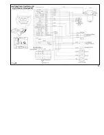
Circuit Diagram.
(Opposite page).
Fig.22
1. Fuel Shutdown Solenoid 20. Bulb c/w Holder
2. Horn
21. Limit Switch
3. Hour Meter
22. ‘Ground’ Cable
4. Glow Plugs ‘ON’ Light 23. Cable.Batt. to Starter
5. Alternator Light
24. Terminal Cover
6. Oil Press. Light
25. Panel Switch
7. Fuse Block
26. Ground Bar
8. Fuse. 20 Amp.
27. Fuse. 5 Amp.
9. Fuse. 10 Amp 28. Strobe Light
10. Water Temperature
29. Ignition Switch
11. Oil Temperature
30. Alternator
12. Work-light 31. Oil Pressure Switch
13. Bulb. 12V 55W 32. Starter Motor
14. Sender-Oil Temperature 33. Glow Plugs
15. Sender-Water Temp. 34. Back-up Alarm
16. Battery 35. F.N.R. Control
17. Panel Switch-Lights
18. Panel Switch- Brake
19. Horn Button
Summary of Contents for 4500
Page 1: ...KESMAC Transportable Forklifts Operators Manual ...
Page 3: ......
Page 9: ......
Page 10: ......
Page 11: ......
Page 12: ...11 3 10 4 8 1 5 7 6 2 9 REAR WHEEL BATTERY ENGINE COMPARTMENT 9 ...
Page 38: ...35 Fig 22 ...
Page 40: ...Fig 25 37 ...


