IntelliGear Plus
TM
Variable Speed Gearmotors and Motors
3.6
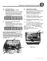
Power supply and control for FCR brake motors
3.6.1 Power supply for the built-in sequential control
brake
ESFR option (31 and 32 only)
- the brake is supplied via the rectifier and a solid
state relay fixed on the ESFR connection card.
This connection is made at the factory.
- The rectifier is supplied by two mains phases.
- The brake is controlled according to the sequence
which can be adjusted using the IntelliGear Plus
parameters.
3.6.2 Separate power supply
The brake is supplied and controlled by an external
source not supplied by Regal Power Transmission
Solutions.
3.7
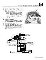
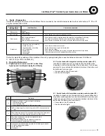
Wiring diagrams for ESFR option
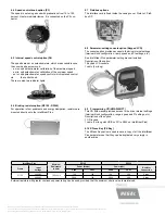
3.7.1 Connection of the ESFR option (31 and 32 only)
Use of this option to power a second motor and
brake is a special and must be specified at order
entry. The illustration for the wiring for the second
motor in the diagram will not apply when this special
feature is not specified.
Coil
brake
Full-wave
(208 - 230VAC
mains supply)
Half-wave
(380 - 460VAC
mains supply)
Power supply to 2nd brake
(mains voltage output)
Power supply to 2nd brake
(mains voltage output)
*Note:With single
phase drive, connect
power supply
between L and N.
Flex-trip to connector
for options
CG
L1
L3
ESFR
CG
230 / 460V
mains supply*
L1
F1
U
V
W
F2
L2 L3
Brake
S06
U
W
V
180VDC
400 / 460V mains supply
230V mains supply
ESFR Card
MCIM15100E • Form 9112E • Printed in USA
17

