IntelliGear Plus
TM
Variable Speed Gearmotors and Motors
5 Faults - Diagnostics
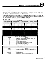
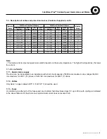
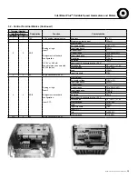
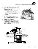
Information relating to the status of the IntelliGear Plus is provided by two indicator lamps located on the control options P1, P2 or P3
or by the internal LED in 31/32.
The fault is cleared by switching off the IntelliGear Plus or by opening/closing the connection between terminals 12: ENA and
11: +24V (31/32) or SDI1 and SDI2 (33).
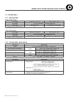
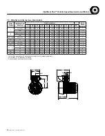
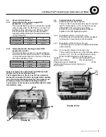
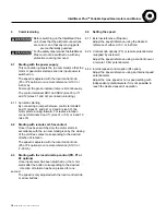
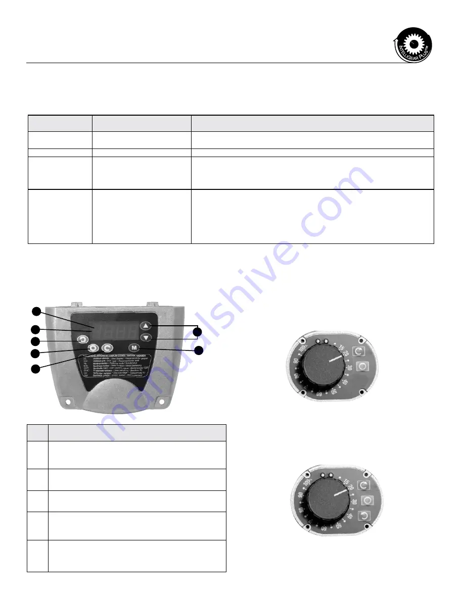
6.2 Control knob with integrated run/stop control option (P1)
In addition to speed control, a run button and a stop button make
it possible to control the IntelliGear Plus locally, once it is has been
powered. For a run command to be taken into account, the button must
be held down for one second.
• It is connected on the P2 connector.
• Has two indicator lights.
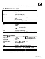
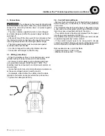
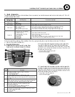
6.3 Control knob with forward/reverse/stop control option (P2)
In addition to speed control, a forward button, a reverse button and a
stop button make it possible to control the IntelliGear Plus locally, once
it has been powered. For a run command to be taken into account, the
button must be held down for one second.
• Connected on the P2 connector
• Has two indicator lights
6 Operating Extensions
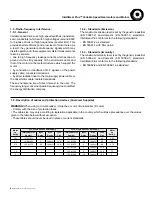
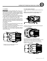
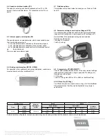
6.1 Digital Keypad on enclosure with For./Rev./Stop/
Speedup and down/Speed display/Fault Display
E
B
F
G
C
D
A
Color and state of
indicator lamp
IntelliGear Plus
Checks to be performed
Steady green
No trip
Mains present
-
Flashing green
Current limiting
• Check that the motor is not overloaded or stalled.
Flashing red
IGBT temperature alarm
Motor overload
Braking resistor option overload
• Check that air is able to circulate around the motor fins and IntelliGear Plus casing.
• The motor is overloaded: check the motor current using a clamp ammeter.
• Check that the deceleration ramp is long enough for applications with high inertia.
Steady red
• Short-circuit of a motor winding
• Locked motor rotor
• Faulty insulation of a winding
• (I2T) overheating
• Internal fault
• Undervoltage
• Overvoltage"
• Check that no incident has occurred.
• Switch off and then on again to clear the fault.
• Check the main voltage.
• Check that the deceleration ramp is long enough for applications with high inertia.
• If the fault remains, consult Regal Application Engineering
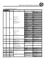
Ref.
Function
A
Display comprising 4 x 7 segment digits for indicating:
- the drive operating status
- certain operating data
- the adjustment parameters (01 to 80) and their value
B
LED providing a sign for the data sign) (the lit LED corresponds to the
"-" sign
C
Keys which can be used to scroll up and down through the parameters
or their value. These keys can also be used to vary the speed.
D
Key which can be used to switch from standard mode to
parameter-setting mode.
In parameter-setting mode, the parameter number and
value are displayed alternately on the display.
E F G
In keypad mode, these buttons are used for the following commands:
- Reverse (standardly disabled)
- Stop, clear fault
- Forward"
MCIM15100E • Form 9112E • Printed in USA
19

