


Broyce Control Ltd., Pool Street, Wolverhampton, West Midlands WV2 4HN. England
Tel: +44 (0) 1902 773746 Fax: +44 (0) 1902 420639 Email: sales@broycecontrol.com Web: www.broycecontrol.com
The information provided in this literature is believed to be accurate (subject to change without prior notice); however, use of such information shall be entirely at the user’s own risk
.
P9680[C]-5-A.DOCX
2
2
2
2
2006
•
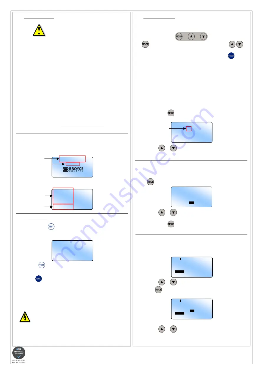
PROGRAMMING
Programming/setting of the
P9680
P9680
P9680
P9680
is carried out using the 3 buttons located
behind the transparent cover.
The
button selects the required parameter to be changed. The
buttons either increment or decrement a value accordingly.
Any adjustments made are stored by the pressing and holding of the
button
until the LCD shows the word “Saved!
Saved!
Saved!
Saved!” See Section 7. SAVING OF SETTINGS.
Please read the
“Notes during programming”
before commencing with the
following.
1A. TOROID RATIO
Setting the Toroid Ratio will allow the “actual” Phase currents (IL1, IL2, IL3) and
Neutral current (Io) displayed on the LCD to represent that of the currents flowing
through the external CT’s. If no CT’s are used, the parameter should be set to 5/5
(i.e. 1:1). The setting applies to all CT’s.
Default setting is “5/5”
•
Press and hold the
button. The LCD displays a screen showing the
characters “User Settings
User Settings
User Settings
User Settings” then the following screen appears…
•
Press either
or
to set the primary value of the external CT’s.
The digit after the forward slash “/” cannot be changed.
1B. NETWORK FREQUENCY
Default setting is “50Hz”
•
Whilst in the same screen as that for the Toroid Ratio (see 1A.), press
the
button to display the options for NETWORK FREQUENCY
NETWORK FREQUENCY
NETWORK FREQUENCY
NETWORK FREQUENCY.
•
Press either
or
to select between 50Hz or 60Hz. This should be
set to suit the frequency of the network being monitored.
•
Press and hold the
button to set the options for “Relay 1”
“Relay 1”
“Relay 1”
“Relay 1” as described
in the next section.
2. RELAY 1 SETTING
Default setting for Relay 1 is linked to “O/C & E/F”. Resetting mode is Manual.
•
The LCD displays the following screen. The options under
“1:”
are displayed
and the default setting highlighted.
•
Press either
or
to select how Relay 1 is assigned to tripping.
•
Press the
button and the options under “2:
2:
2:
2:” for resetting are displayed
and the default setting highlighted.
Actual LCD presentation when adjustable parameters are displayed.
•
Press either
or
to select between AUTO
AUTO
AUTO
AUTO resetting or MAN
MAN
MAN
MANUAL
resetting (after a fault has occurred).
continued on next page…
•
INSTALLATION
•
BEFORE INSTALLATION, ISOLATE THE SUPPLY. THIS PRODUCT IS
DESIGNED TO CONNECT TO SEVERAL TYPES OF CIRCUITS.
ENSURE ALL ARE ISOLATED^
•
Remove the
P9680
P9680
P9680
P9680
from the packaging.
•
Lift the raised part of the side clip in order to withdraw from the housing.
Carry this out on each side.
•
Insert the
P9680
P9680
P9680
P9680
into the panel cut-out and fit the side clips back on to the
housing.
•
Slide the clips towards the front of the unit until they come in to contact with
the reverse of the panel. The unit is now secured in place.
•
Wire the supplied female pluggable connectors as required.
•
Plug the connectors into the relevant sockets on the rear of the unit.
•
The
P9680
P9680
P9680
P9680
is now ready for powering and programming.
The front window of the P9680 is supplied with a clear protective film which can be
removed as and when necessary.
^ When carrying out future maintenance on the product or application and it
becomes necessary to disconnect the connectors from the product, ensure for the
Current Transformer connector, they do not remain open circuit
they do not remain open circuit
they do not remain open circuit
they do not remain open circuit. This can lead to
high voltages being present on this connector.
•
NORMAL OPERATION
•
Apply power to the unit and the green
“Power supply”
LED will illuminate.
•
The LCD will momentarily display a welcome screen as shown…
….then after a short delay reverts to indicating the following information:
•
TEST MODE
•
Press and hold the
button and both relays will energise. The LCD will
display the characters
“TEST”
and the product part number (as below). The
LCD backlight and red
“Trip”
LED will flash.
•
Release the
button and the relay(s) will remain energised if set to Manual
reset or de-energise if set to Auto reset.
•
Press the
to de-energise relay(s) which are set to Manual reset. The
LCD will revert back to Normal operation. The LCD backlight and red
“Trip
” LED will stop flashing.
Testing should be carried out on a regular basis to check the integrity of the
P9680.
DO NOT use this product to provide a means of isolating circuits in
order to work on when placed in the “TEST”
“TEST”
“TEST”
“TEST” mode. This should only be
done by means of operating isolators, circuit breakers or other
methods of removing power in this application.
I
L1
0.00
A
I
L2
0.00
A
I
L3
0.00
A
I
O
0.00
A
Installation work must be carried
out by qualified personnel.
Actual phase
currents
Actual Earth
fault current
TEST
TYPE: P9680
Ver: X.X
TOROID RATIO
5 / 5
RELAY
1
CONFIGURATION
1:
O/C
E/F
O/C & E/F
Digits which
can be adjusted
TYPE: P9680
Ver: X.X
Model No.
Version
TOROID RATIO
5 / 5
NETWORK FREQUENCY
50Hz
60Hz
RELAY
1
CONFIGURATION
1: 2:
O/C AUTO
E/F
MAN
O/C & E/F


