


Broyce Control Ltd., Pool Street, Wolverhampton, West Midlands WV2 4HN. England
Tel: +44 (0) 1902 773746 Fax: +44 (0) 1902 420639 Email: sales@broycecontrol.com Web: www.broycecontrol.com
The information provided in this literature is believed to be accurate (subject to change without prior notice); however, use of such information shall be entirely at the user’s own risk
.
P9680[C]-5-A.DOCX
3
3
3
3
2006
6. MODBUS SETTING (P9680C only)
•
Here there is the option to set the Address, Baud rate and Parity. Use the e
button to select the different parameters.
Actual LCD presentation when adjustable parameters are displayed.
•
Press either
or
to change the parameter values.
•
Press and hold the
button to see a summary of the “OVERCURRENT”
“OVERCURRENT”
“OVERCURRENT”
“OVERCURRENT”
then “EARTH FAULT”
“EARTH FAULT”
“EARTH FAULT”
“EARTH FAULT” settings as described in the next section.
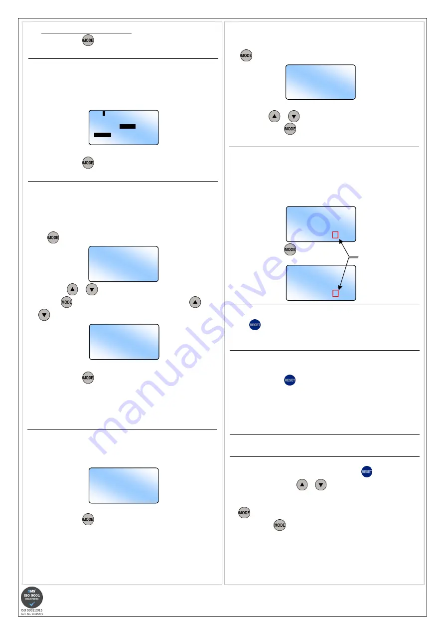
7. OVERCURRENT & EARTH FAULT SUMMARY
It is not possible to edit settings when these screens are displayed.
•
Following the setting of “Earth Fault”, the LCD displays the “Overcurrent
Summary” screen showing a summary of the settings made during
programming. All settings are displayed. The selected CT ratio, Network
Frequency and Relay operation (following a Reset) information is also
displayed.
•
Press and hold the
button to display the
“Earth Fault Summary” screen.
8. SAVING OF SETTINGS
•
If after viewing the Summary screens the settings are correct, press and hold
the
button until the word “Saved.”
“Saved.”
“Saved.”
“Saved.” appears. Any new settings are now
stored.
•
The screen will revert back to Normal operation.
8. QUICK VIEW OF USER SETTINGS
It is not possible to edit settings when these screens are displayed.
This feature can also be activated with the front window closed!
Press and hold the
button to display the initial power up screen.
•
Press the same button again to display the “Last Tripped Information” screen
(
refer to the next page for further information on this feature).
Press again to display the “Overcurrent Summary” screen.
Press again to display the “Earth Fault Summary” screen.
Press again to display the contact details for Broyce Control.
Press again to revert back to Normal operation.
9. LAST TRIPPED INFORMATION
Refer to next page for detailed information of this feature
Notes during programming
If during programming it is necessary to abort, press the
button briefly.
Pressing and holding either
or
for >1sec. will increment or decrement
the new value at a quicker rate.
Stepping through each User Setting screen is performed by pressing and holding
the
button until the desired screen is displayed.
Short presses of the
button will allow further editable settings to be changed
within a specific screen.
If the user remains in a setting or summary screen where no adjustments or button
presses are made within a certain period, the screen will revert back to Normal
operation. Additionally, any settings that have been made but not stored will not be
saved.
”O/C” refers to Overcurrent and “E/F” refers to Earth fault.
•
PROGRAMMING (continued)
•
Press and hold the
button to set the options for “Relay 2”
Relay 2”
Relay 2”
Relay 2” as described
in the next section.
3. RELAY 2 SETTING
Default setting for Relay 2 is linked to “O/C & E/F” and energising at the end of the
time out period. Resetting mode is Auto.
•
Setting of “Relay 2” is carried out in a similar manner as “Relay 1”, however it
is necessary to assign the relay to either energise at the start (S) or end (E) of
the time out period.
Actual LCD presentation when adjustable parameters are displayed.
•
Press and hold the
button to set the options for “OVERCURRENT”
“OVERCURRENT”
“OVERCURRENT”
“OVERCURRENT” as
described in the next section.
4. OVERCURRENT SETTING
The description for the Curves is abbreviated when displayed on the screen. Refer
to “IDMT Characteristic Curves” for further explanation.
Default settings for Overcurrent are shown in the last LCD screen example in this
section.
•
Settings for Overcurrent are displayed in turn following subsequent presses of
the
button. The Low-set trip current (I>) is displayed first.
•
Press either
or
to change the current.
•
Press the
button to select the remaining settings and use the
and
buttons to change them.
Actual LCD presentation when adjustable parameters are displayed.
Screen example above also shows the default settings for OVERCURRENT.
•
Press and hold the
button to set the options for “EARTH FAULT”
“EARTH FAULT”
“EARTH FAULT”
“EARTH FAULT” as
described in the next section.
If the Curve in selection “2:” is set to Definite Time, then selection “3:” will display
“3: t>” and the required delay can then be set.
If High-set is set to Disable in selection “4:”, then I>> or t>> cannot be
adjusted.
5. EARTH FAULT SETTING
Default settings for Earth Fault are shown in the LCD screen example in this
section.
•
Settings for Earth Fault are carried out the same as described for Overcurrent.
Screen example showing the default settings for EARTH FAULT.
•
Press and hold the
button for either:
•
Summary of the “OVERCURRENT”
“OVERCURRENT”
“OVERCURRENT”
“OVERCURRENT” then “EARTH FAULT”
“EARTH FAULT”
“EARTH FAULT”
“EARTH FAULT” settings
(Model: P9680)
•
Option to change the MODBUS settings (Model: P9680C)
If the Curve in selection “2:” is set to Definite Time, then selection “3:” will display
“3: to>” and the required delay can then be set.
If High-set is set to Disable in selection “4:”, then Io>> or to>> cannot be
adjusted.
O/C SETTING
Low set
1: I> 5.00A
RELAY
2
CONFIGURATION
1: 2:
O/C
AUTO (E)
E/F MAN (E)
O/C & E/F
AUTO (S)
MAN (S)
O/C SETTING
Low Set:
1: I> 5.00A
2: Curve NI 3/10
3: k> 0.1
High Set:
4: I>> 50.00A
5: t>> 0.05s
E/F SETTING
Low Set:
1: Io> 2.00A
2: Curve NI 3/10
3: k> 0.1
High Set:
4: Io>> 10.00A
5: to>> 0.05s
O/C SUMMARY
I> 5.00A
NI 3/10
k> 0.1
I>>50.00A
t>>0.05s
R1 = MAN R2 = AUTO (E)
CT=5:5, FREQ=50Hz
E/F SUMMARY
Io> 2.00A
NI 3/10
ko> 0.1
Io>>10.00A
to>>0.05s
R1 = MAN R2 = AUTO (E)
CT=5:5, FREQ=50Hz
The letter in brackets refers to
whether Relay 2 has been set
to trigger at the start or end of
the time out period.
(E) = E
EE
End of time out
(S) = S
SS
Start of time out
Either abbreviation can appear
after the word MAN or AUTO
See Section 3. RELAY 2
SETTING
MODBUS
ADDR 1
BAUD 9600
PARITY None


