


Broyce Control Ltd., Pool Street, Wolverhampton, West Midlands WV2 4HN. England
Tel: +44 (0) 1902 773746 Fax: +44 (0) 1902 420639 Email: sales@broycecontrol.com Web: www.broycecontrol.com
The information provided in this literature is believed to be accurate (subject to change without prior notice); however, use of such information shall be entirely at the user’s own risk
.
P9680[C]-5-A.DOCX
4
4
4
4
2006
•
PROGRAMMING (continued)
9A. LAST TRIPPED INFORMATION
This information is held in memory even if power is removed.
This feature allows the user to view and recall the key information relating to the last trip event and it can store up to 10 trip events. It is accessed as described in Section 8
on the previous page.
The information displayed highlights the cause of the trip (i.e. which phase for example), the level of current at the time the trip occurred; the triggering method (Low-set
or High-set) and which relays were activated. It also shows the elapsed time from powering the
P9680
P9680
P9680
P9680
to the trip occurring and displayed against “Ttrip” as well as showing
the time difference between the trip displayed and the one previous to that. This is shown against “Tdiff”.
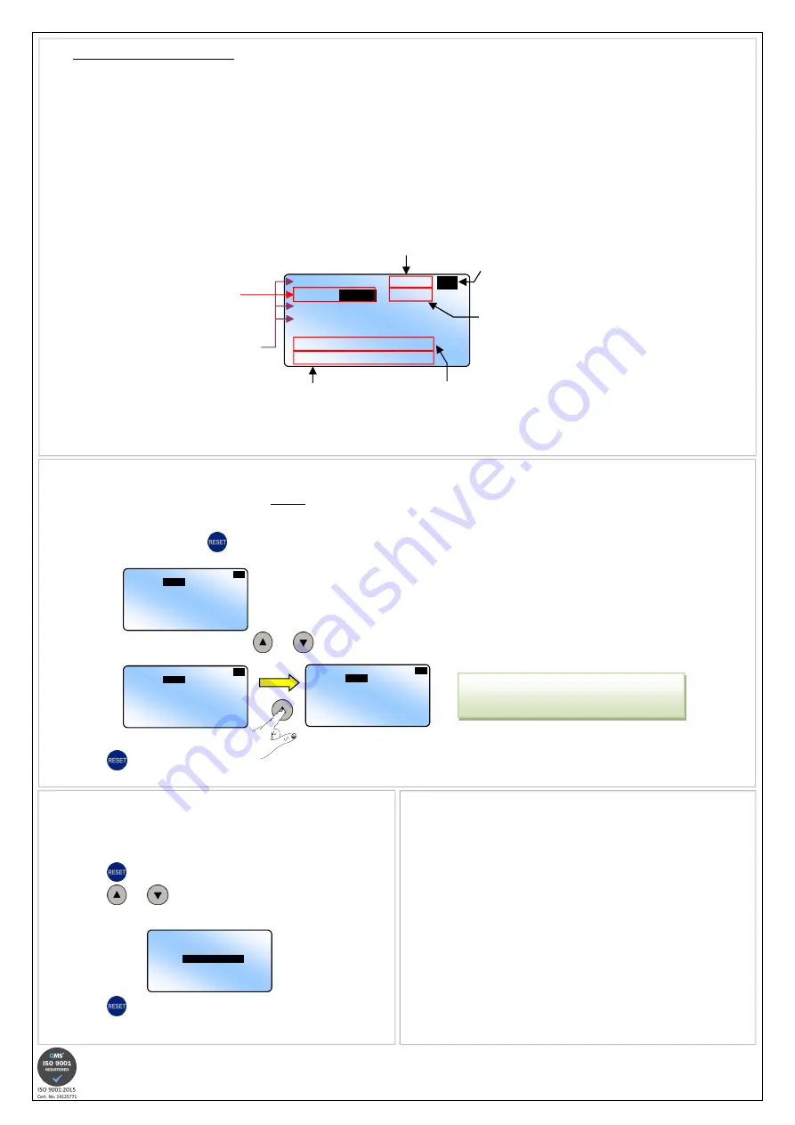
An example of the screen layout is shown below.
If there is only one trip event stored in the memory, the display will show “Tdiff: ----d--h--m--s” when viewed.
Phase which
caused the trip
to occur
(i.e. L2)
Level of current
on other inputs
at time of trip
Trip number
(1…10)
Relays that were
activated at trip
IL1 20.70A I>>
1
…
IL2
89.00A
R1 R2
IL3 27.50A
Io 0.00A
Ttrip: 0000d00h00m00s
Tdiff: 0000d00h00m00s
Level which was
triggered (i.e. High-set)
9B. RECALLING THE LAST TRIPPED INFORMATION
If the unit has logged the maximum number of trips which can be stored, then the display will show “Tdiff: ----d--h--m--s” when trip screen 10 is viewed.
The screen will revert back to Normal operation after 1 minute if no further button presses are made.
If a trip condition occurs whilst in this mode, the screen will automatically change to display the information relating to the current status.
•
As described in Section 8, use the
to gain access to the Last Tripped Information screen. The display will show the most recent trip information as follows:
•
If more than one trip event is stored, use the
and
buttons to select the screens accordingly.
•
Press the
button to exit the screen information when finished or allow to time out automatically.
IL1
1.65A
I>
1
…
IL2
15.00A
R1 R2
IL3 8.40A
Io 0.00A
Ttrip: 0001d13h15m04s
Tdiff: - - - -d - -h - -m - -s
IL1
1.65A
I>
1
…
IL2
15.00A
R1 R2
IL3 8.40A
Io 0.00A
Ttrip: 0001d19h24m56s
Tdiff: 0000d06h09m52s
IL1
1.80A
I>
2
…
IL2
21.35A
R1 R2
IL3 9.20A
Io 0.00A
Ttrip: 0001d13h15m04s
Tdiff: - - - -d - -h - -m - -s
Ttrip:
The elapsed time from
applying power to the
current trip
Tdiff:
The time difference
between the current trip
and the previous trip
The example on the left shows the problem on phase L2 on
both trip events. The difference between the first recorded
trip and second was 6h 09m
6h 09m
6h 09m
6h 09m and 52s
52s
52s
52s.
9C. CLEARING THE LAST TRIPPED INFORMATION HISTORY
Once the information has been deleted, it will not be possible to recall this.
“Ttrip” information is still retained but won’t be displayed after the carrying out this
operation (See 9D)
•
Press the
button to access the relevant screen.
•
Press the
and
buttons simultaneously to delete the information.
When this is complete, the screen will show:
•
Press the
button again to exit.
No previous trip info
9D. CLEARING “Ttrip” INFORMATION
If the tripping history hasn’t been deleted, previous information will be displayed
from the last time the unit was powered up.
•
The “Ttrip” information will still be held in memory after deleting the trip
history is made and also if power is removed and re-applied. However,
when power is re-applied, the internal counter will reset and start from zero
•
Only when a new trip condition occurs will the “Ttrip” information get
updated and be displayed on the most recent screen.


